
Optical interferometer and signal synthesizer using the interferometer
a signal synthesizer and interferometer technology, applied in the direction of optical radiation measurement, instruments, measurement devices, etc., can solve the problems of insufficient consideration of controlling the spectral components the narrow spectral spectrum of the pulse, and the inability to control the spectra of the output optical puls
Patent Information
- Authority / Receiving Office
- US · United States
- Patent Type
- Patents(United States)
- Current Assignee / Owner
- Publication Date
- 2000-07-18
- Estimated Expiration
- Not applicable · inactive patent
Smart Images
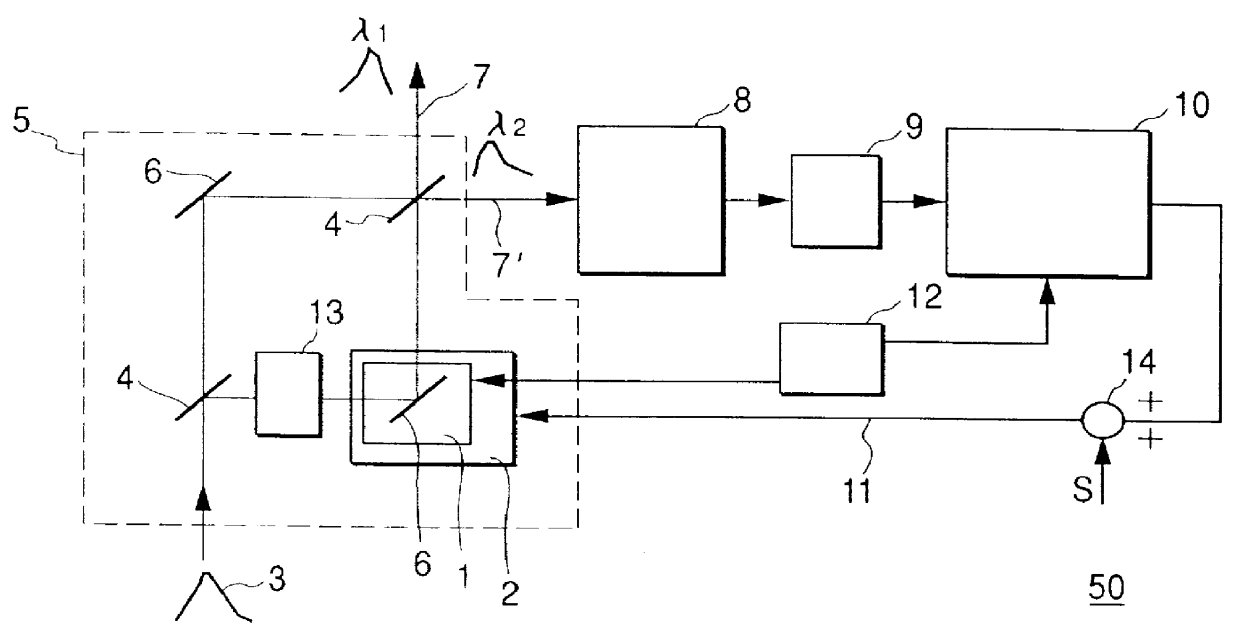
Figure 1 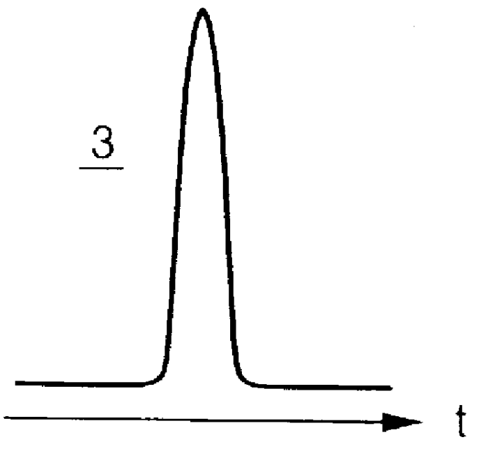
Figure 2 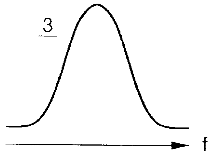
Figure 3
Abstract
Description
1. Field of the InventionThis invention relates to an optical interferometer and a signal synthesizer, and particularly to an optical interferometer applied to an optoelectronic device for performing signal processes for operations or communications, which are emploing optical pulses and a signal synthesizer using the optical interferometer.2. Description of the Related ArtOn / off switching of output optical pulses using the difference in phase between two optical paths of a Mach-Zehnder interferometer is a well-known technique. However, since a long pulse of sub-nanoseconds or so has heretofore been used, the spectrum of the pulse is very narrow. Further, the conventional Mach-Zehnder interferometer controls the intensities of the output optical pulses but encounters difficulties in controlling their spectra.The prior art has a problem in that although it performs intensity modulation on the output optical pulses with respect to relatively long pulse of sub-nanoseconds or so, the co...
Examples
embodiment ii
[EMBODIMENT II]
FIG. 3 is a block diagram showing a signal synthesizer for controlling pulses .lambda..sub.1 and .lambda..sub.2 outputted from a phase-locked interferometer 50 according to 1 / 0 of a modulating signal S and an example in which communications are made by the signal synthesizer.
As described in relation to FIG. 1A, when a voltage having a suitable magnitude is applied to the addition circuit 14 in response to 1 / 0 of the modulating signal S, the error would be as if to have occurred in the optical path difference correspondingly. For example, the difference between the two optical-paths 7 an 7' is reversed so that output optical pulses having spectra .lambda..sub.1 and .lambda..sub.2 can be obtained from their corresponding optical paths 7 and 7'. Namely, the phase-locked interferometer can be constructed as the signal synthesizer by controlling the optical path difference of the interferometer 5. An incident pulse 3 is supplied to the phase-locked interferometer 50 and a ...
embodiment iii
[EMBODIMENT III]
In the present embodiment, an output spectrum obtained from an optical path 7 or 7' of a phase-locked interferometer 50 is set so as to have a number of central frequencies as shown in FIGS. 2C and 2D and it is controlled so as to be held constant. The output optical pulse obtained from either one of the optical paths 7 and 7' is spatially separated into parallel beams by prisms 61 and 62. Thereafter, an absorption light modulator 63 is placed on optical paths of the parallel beams. A one-dimensionally space-dependent light modulator using a liquid crystal, which will be described later as a specific example, was used as the light modulator 63. The light modulator 63 is supplied with a signal S to control the turning on and off of frequencies corresponding to respective locations or places for the light modulator 63. After the parallel beams are gathered again by prisms 64 and 65, they are allowed to pass through an optical transfer medium 19. Here, lenses may be use...
embodiment iv
[EMBODIMENT IV]
In the present embodiment, a phase-locked interferometer will be explained, which makes use of both the aforementioned optical paths 7 and 7' and mounts them on a semiconductor substrate. FIG. 5 is a block diagram showing a basic configuration of the phase-locked interferometer and draws even signal waveforms at respective input / output positions side by side together with the configuration of the phase-locked interferometer. Reference numeral 100 indicates a Mach-Zehnder interferometer of two optical paths, into which an optical pulse 3 having the continues spectrum and time characteristics shown in FIGS. 1B and 1C is launched. The output of the interferometer 100 is divided into two whose respective spectra result in discrete spectra like .lambda..sub.1 and .lambda..sub.2. Now consider that the respective peaks of the spectrum .lambda..sub.1 fall within frequencies f.sub.1, f.sub.3, f.sub.5, . . . , respectively whereas the respective peaks of the spectrum .lambda..s...