
Method and system for facilitating location-based services
a technology of location and service, applied in the field of communication systems, can solve the problems of burdensome in practice, difficult for users to enter text information such as street addresses, and require substantial modification of existing networks
Patent Information
- Authority / Receiving Office
- US · United States
- Current Assignee / Owner
- Publication Date
- 2004-11-09
- Estimated Expiration
- Not applicable · inactive patent
Smart Images
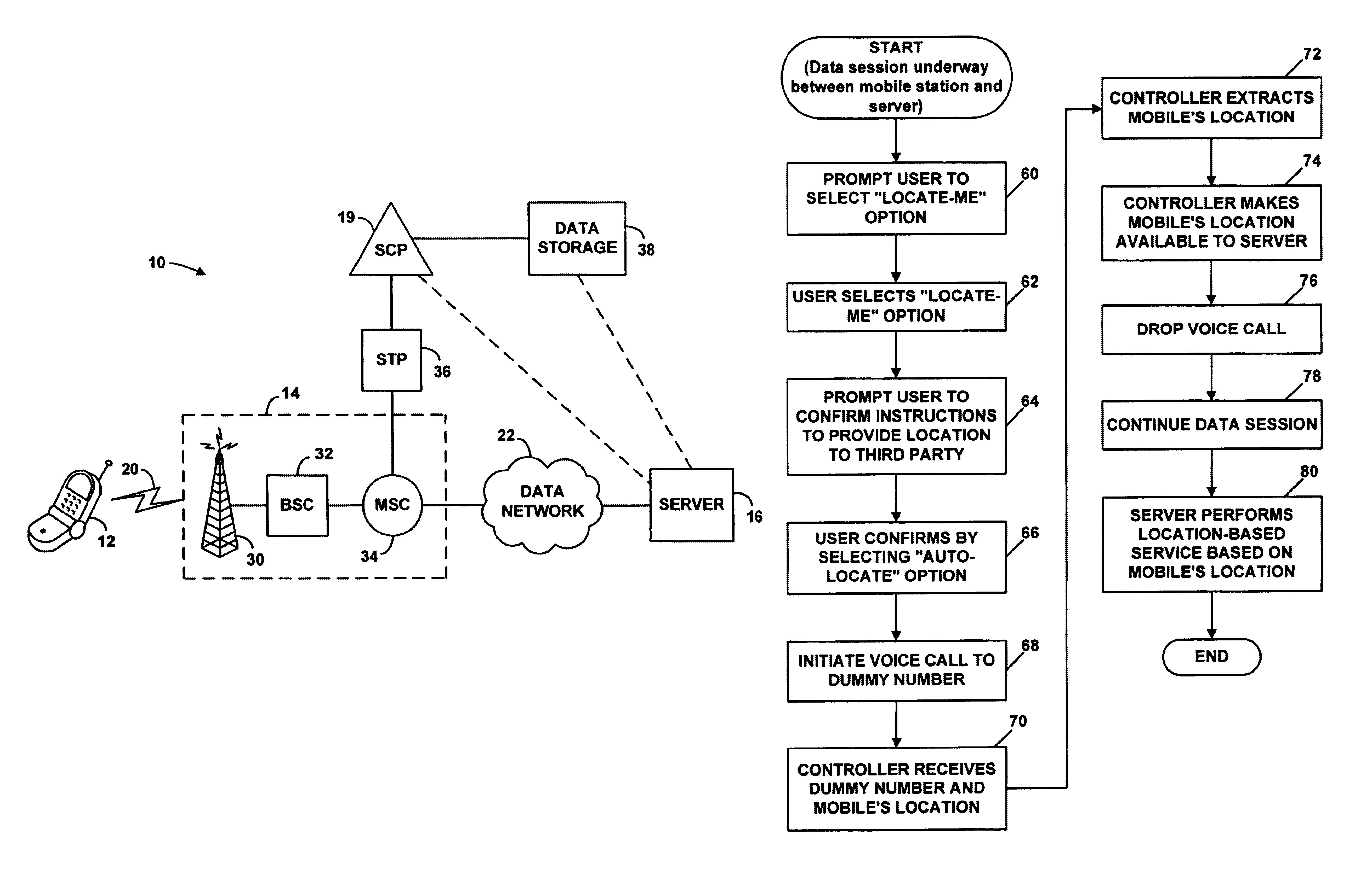
Figure 1 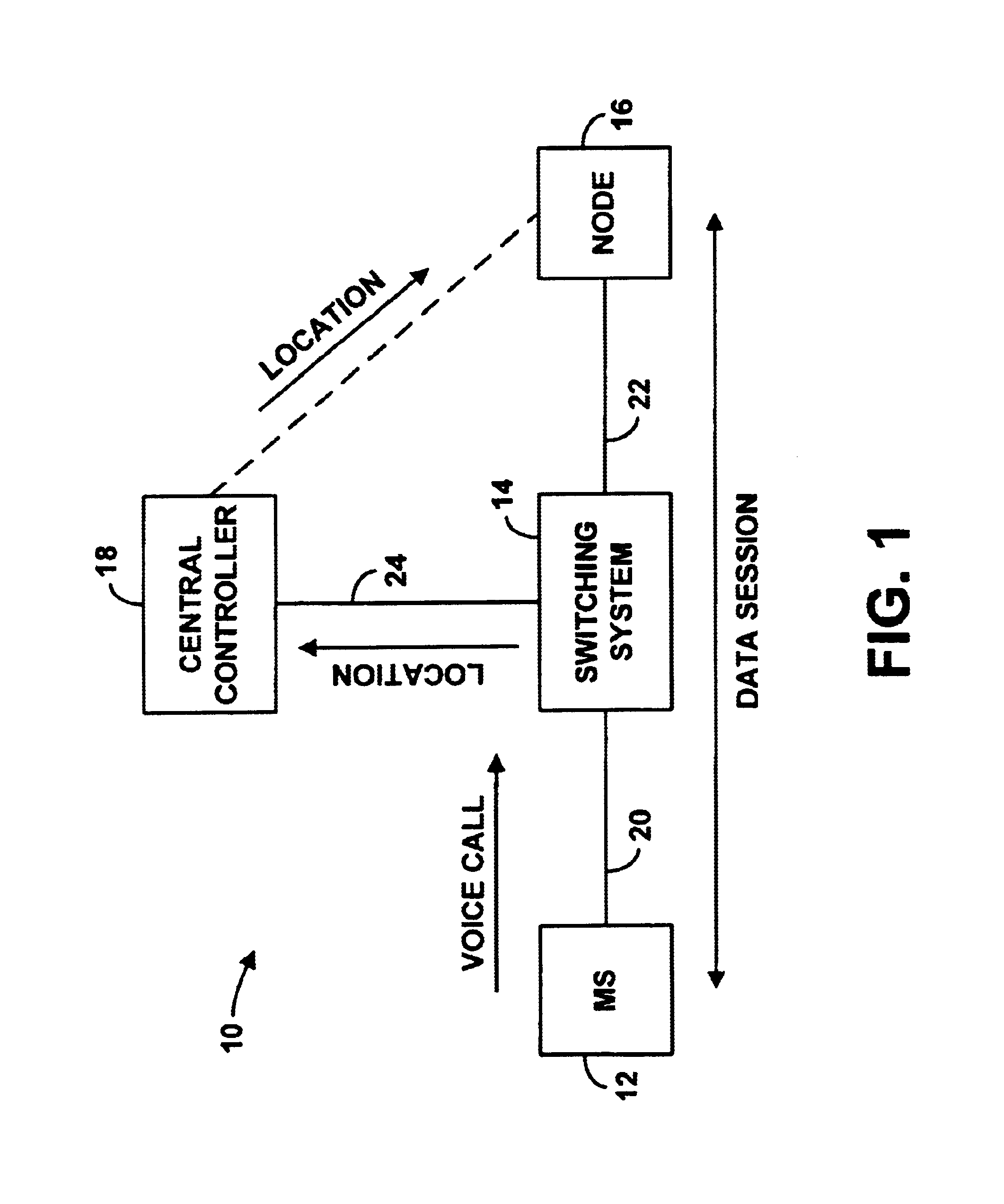
Figure 2 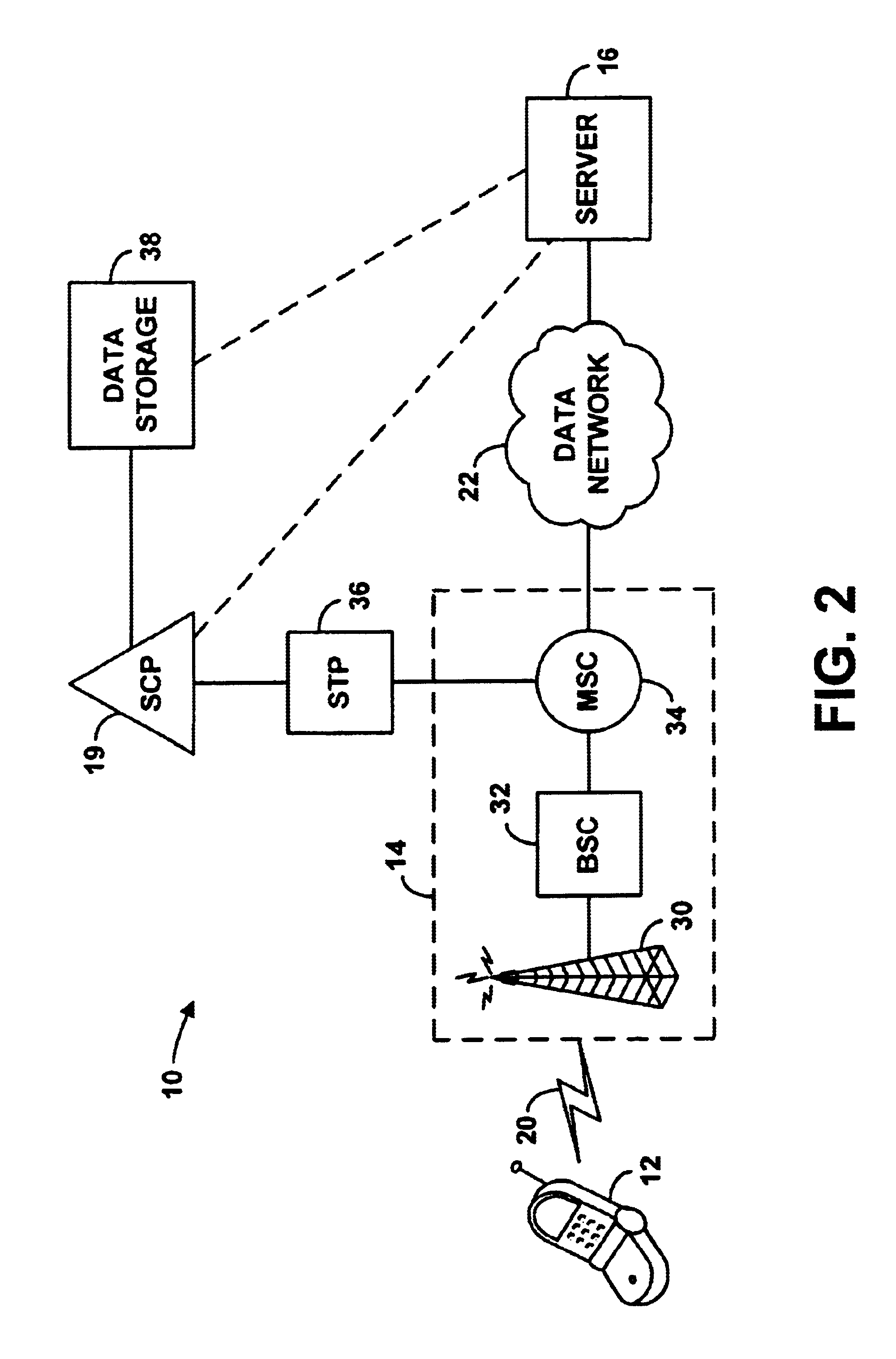
Figure 3
Abstract
Description
1. Field of the InventionThe present invention relates to communications systems and, more particularly, to methods and systems for determining the location of mobile stations, such as cellular telephones, personal data assistants (PDAs), or notebook computers for instance.2. Description of Related ArtMobile stations that enable voice and data communications over an air interface are now commonplace. In a typical arrangement, a mobile station communicates via an air interface with a radio access system, which provides connectivity with a larger communications network such as the public switched telephone network (PSTN), an intranet or the Internet for instance. The radio access system may typically include a base transceiver station (BTS) (having an antenna that provides a radiation pattern defining the air interface), which is coupled or integrated with a base station controller (BSC). The BSC may then be coupled or integrated with a switch (e.g., a mobile switching center (MSC)) o...
Examples
Embodiment Construction
1. Exemplary Architecture
Referring to FIG. 1, there is shown a simplified block diagram depicting a system 10 in which an exemplary embodiment of the present invention can be employed. As shown in FIG. 1, system 10 includes an exemplary mobile station 12, a switching system 14, a remote node 16, and a central controller 18. Mobile station 12 is shown being communicatively coupled with switching system 14 by an interface 20, and node 16 is shown being communicatively coupled with switching system 14 by an interface 22. Additionally, switching system 14 is shown being communicatively coupled with central controller 18 via an interface 24. Finally, a communication interface 26 is shown between central controller 18 and node 16.
It should be understood that this and other arrangements described herein are illustrative only, and that other arrangements are possible as well. For instance, other elements (e.g., machines, interfaces, functions, etc.) can be used instead, and some elements ma...