
System for illuminating an object
a technology of illuminating systems and objects, applied in the field of navigational engineering, can solve the problems of low reliability, low speed response of above-mentioned coordinators, and known systems that fail to provide high accuracy of measuring and achieve the effect of higher measuring accuracy of angular coordinates of targets
Patent Information
- Authority / Receiving Office
- US · United States
- Patent Type
- Patents(United States)
- Current Assignee / Owner
- Publication Date
- 2005-05-31
- Estimated Expiration
- Not applicable · inactive patent
Smart Images
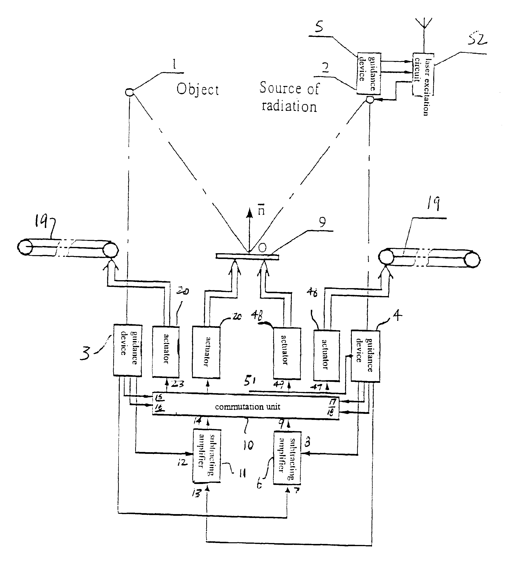
Figure 1 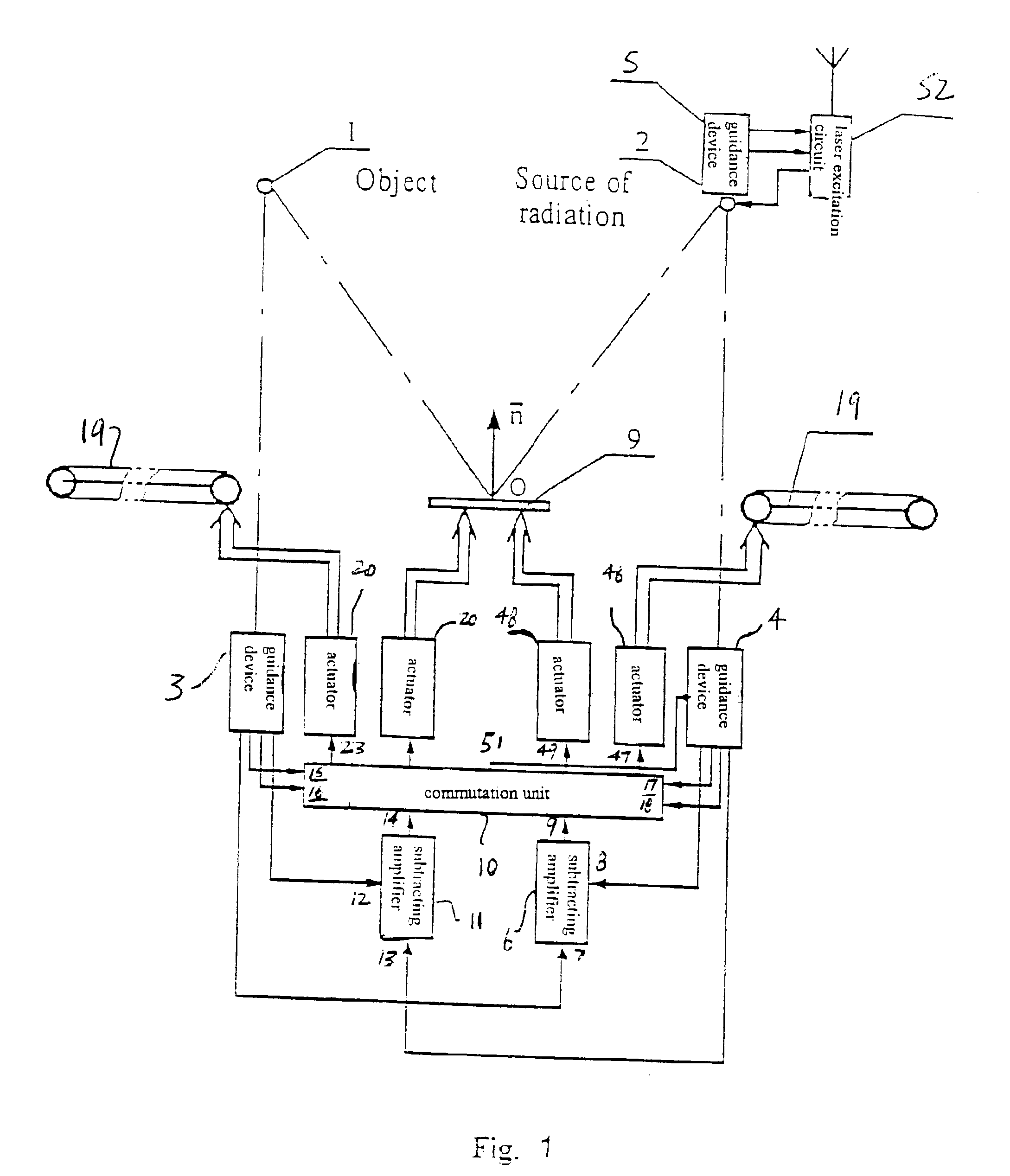
Figure 2 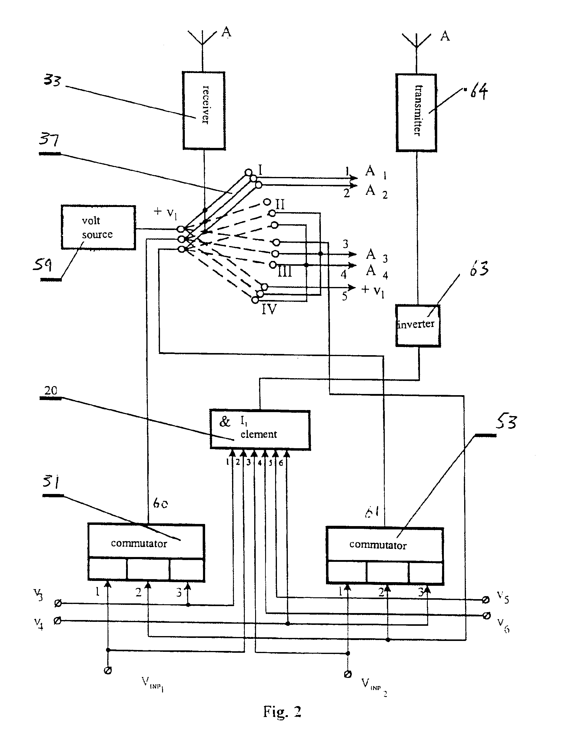
Figure 3
Abstract
Description
CROSS REFERENCE TO RELATED APPLICATIONS
[0001] Applicants claim priority under 35 U.S.C. §119 of Russian Application No. 99111294 filed May 28, 1999. Applicants also claim priority under 35 U.S.C. §120 of PCT / RU00 / 00144 filed Apr. 21, 2000. The international application under PCT article 21(2) was not published in English.TECHNICAL FIELD
[0002] The invention relates to navigational engineering, more specifically, to optoelectronic systems for autotracking of moving objects.BACKGROUND ART
[0003] Known in the present state of the art are systems for automatic guidance and tracking of moving targets, which are based on the frequency, phase, pulse-height, time-pulse and amplitude-phase principles and can be used for illumination of objects (cf. L. Z. Kriksunov, I. F. Usoltsev. Infrared systems. Moscow, “Sovetskoye Radio” Publishing House, 1968, p.p. 157-239 (in Russian).
[0004] Known coordinators (target seekers) generate signals, which are proportional to the constituents of the angle of misal...
Examples
Embodiment Construction
[0029]The system for lighting an object 1 (FIG. 1) comprises a radiation source 2 and guidance devices 3, 4, 5, of which the guidance device 3 is optically connected to the object 1, and the device 4, to the radiation source 2. The system further comprises a subtracting amplifier 6 having its inputs 7 and 8 connected to the respective outputs of the guidance devices 3 and 4, while the output thereof is connected to an input 9 of the commutation unit 10, and a subtracting amplifier 11 whose inputs 12 and 5 are connected to the outputs the guidance devices 3 and 4, respectively, and its output is connected to an input 14 of the commutation unit 10. Inputs 15 and 16 of the commutation unit 10 are connected to the corresponding outputs of the guidance device 3, while its inputs 17 and 18 thereof are connected to the respective outputs of the guidance device 4. In addition, the system comprises a mirror 19 with which kinematically coupled are actuators 20 having their inputs connected to...