
Methods of optimizing recording current and setting recording density of hard disk drive
Patent Information
- Authority / Receiving Office
- US · United States
- Current Assignee / Owner
- Publication Date
- 2006-09-05
- Estimated Expiration
- Not applicable · inactive patent
Smart Images
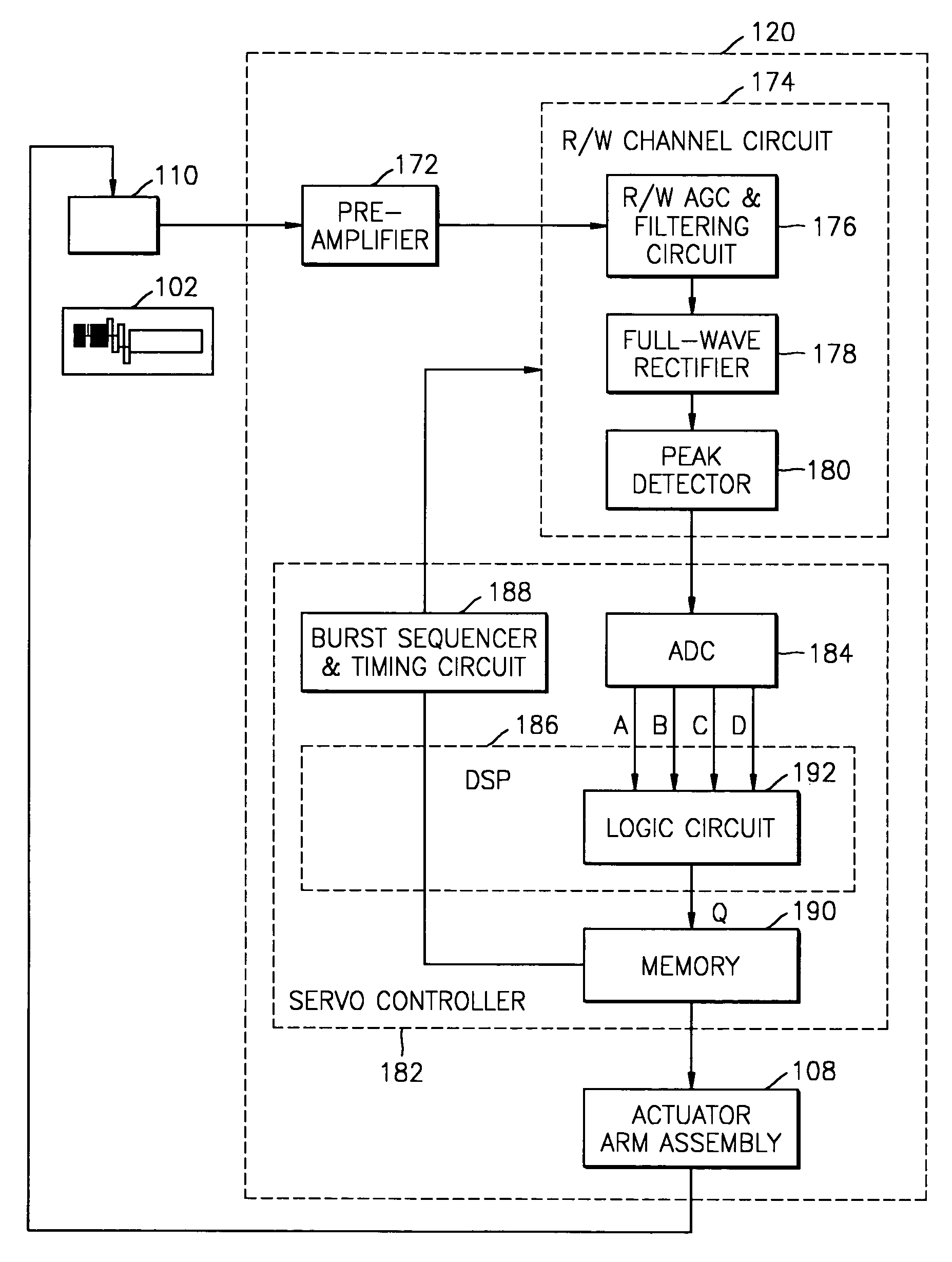
Figure 1 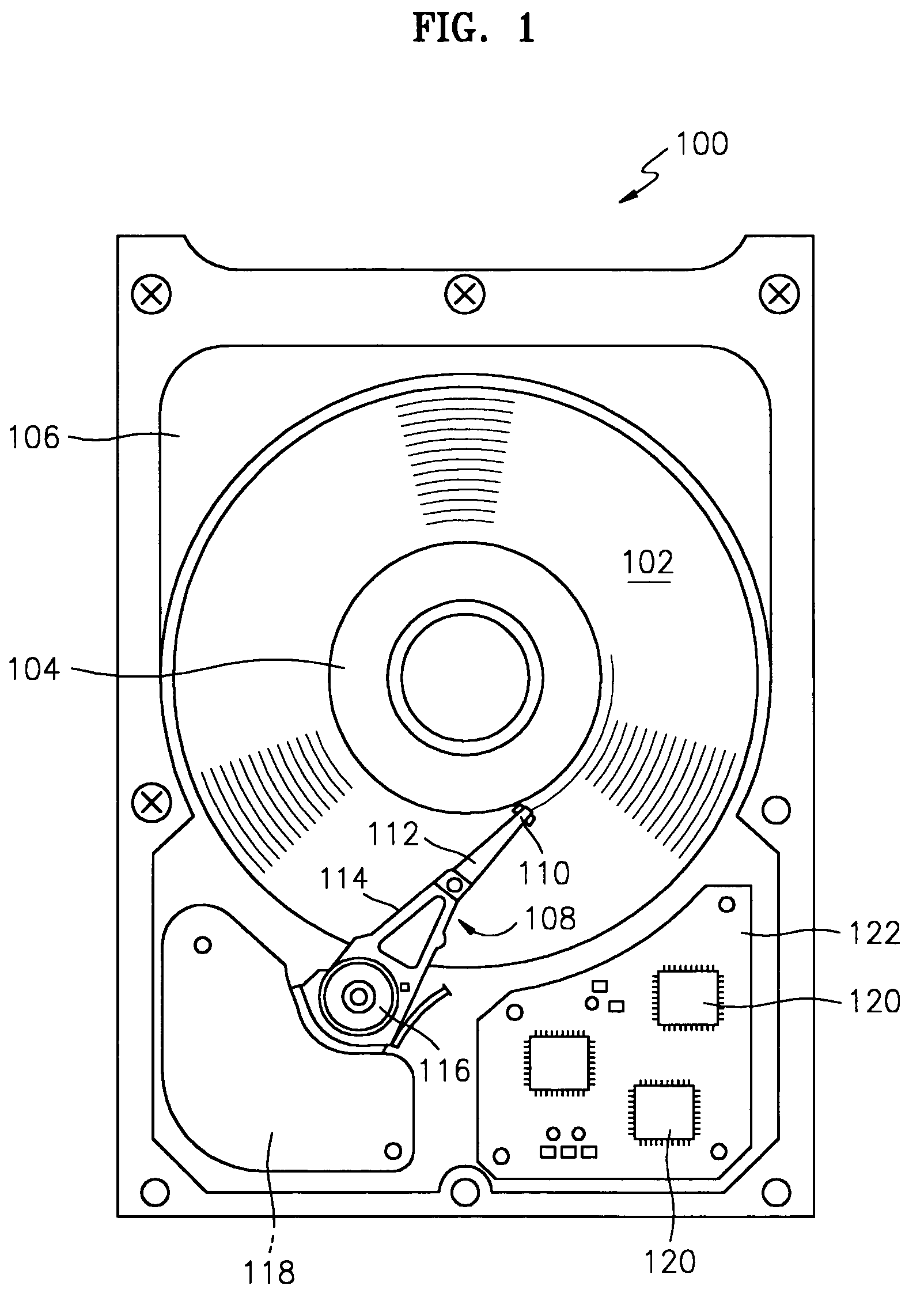
Figure 2 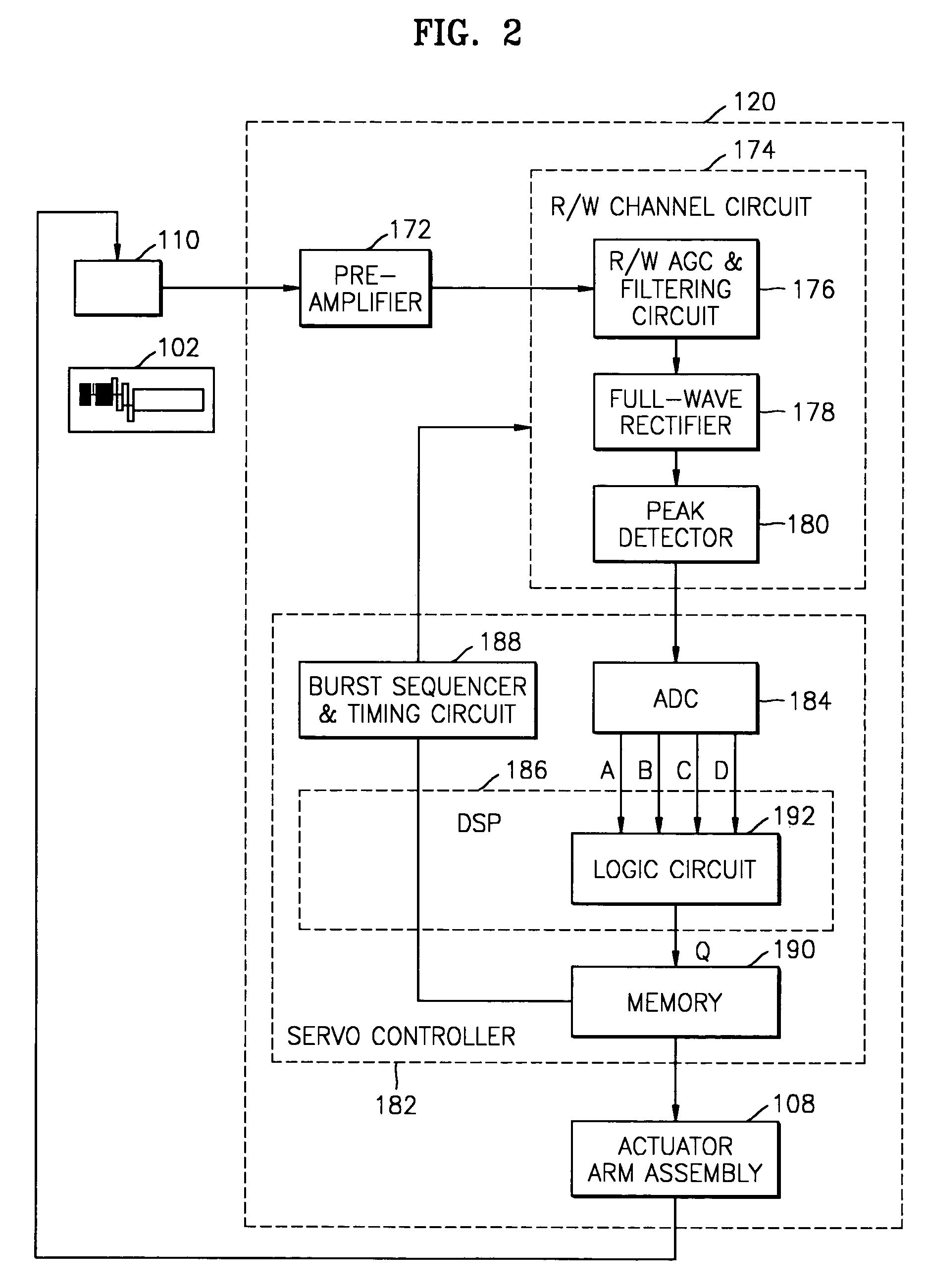
Figure 3
Abstract
Description
CROSS-REFERENCE TO RELATED APPLICATIONS
[0001] This application claims the priority of Korean Patent Application No. 2002-79750 filed Dec. 13, 2002, in the Korean Intellectual Property Office, the disclosure of which is incorporated herein in its entirety by reference.BACKGROUND OF THE INVENTION
[0002] 1. Field of the Invention
[0003] The present invention relates to a hard disk drive, and more particularly, to methods of optimizing a recording current according to an operating environment temperature, and setting tracks per inch (TPI), or recording density, in consideration of the adjacent track erasure (ATE) characteristics of a head.
[0004] 2. Description of the Related Art
[0005] A hard disk drive is a recording device used to store information. In general, tracks are concentric circles formed on a recording surface of a magnetic recording disc, and information is recorded on at least one track. In the hard disk drive, a disk is rotated with respect to a spindle motor, and information is ...
Examples
Embodiment Construction
[0039]Reference will now be made in detail to the embodiments of the present invention, examples of which are illustrated in the accompanying drawings, wherein like reference numerals refer to the like elements throughout. The embodiments are described below to explain the present invention by referring to the figures.
[0040]FIG. 1 illustrates the structure of a hard disk drive 100. The hard disk drive 100 includes a magnetic disk 102 that is rotated by a spin motor 104. The spin motor 104 is mounted on a base plate 106. An actuator arm assembly 108 is also mounted on the base plate 106. The actuator arm assembly 108 includes a plurality of heads 110 coupled to respective suspensions 112. The suspensions 112 are attached to an actuator arm 114 that is rotated with respect to a bearing assembly 116. The actuator arm assembly 108 includes a voice coil 118 coupled to a magnet (not shown) mounted on the base plate 106. When energy is supplied to the voice coil 118, the heads 110 are move...