
Load-controlled device for a patterned skin incision
a skin incision and load control technology, applied in the field of medical devices, can solve the problems of affecting the acceptance of such devices in many countries around the world, devices were significantly more expensive than previous methods, and still subject to a variety of technical variables, so as to minimize the introduction of undesirable elements, reduce the introduction of trauma to the skin, and maintain the effect of pressure on the skin
Patent Information
- Authority / Receiving Office
- US · United States
- Patent Type
- Patents(United States)
- Current Assignee / Owner
- Publication Date
- 2007-01-09
- Estimated Expiration
- Not applicable · inactive patent
Smart Images
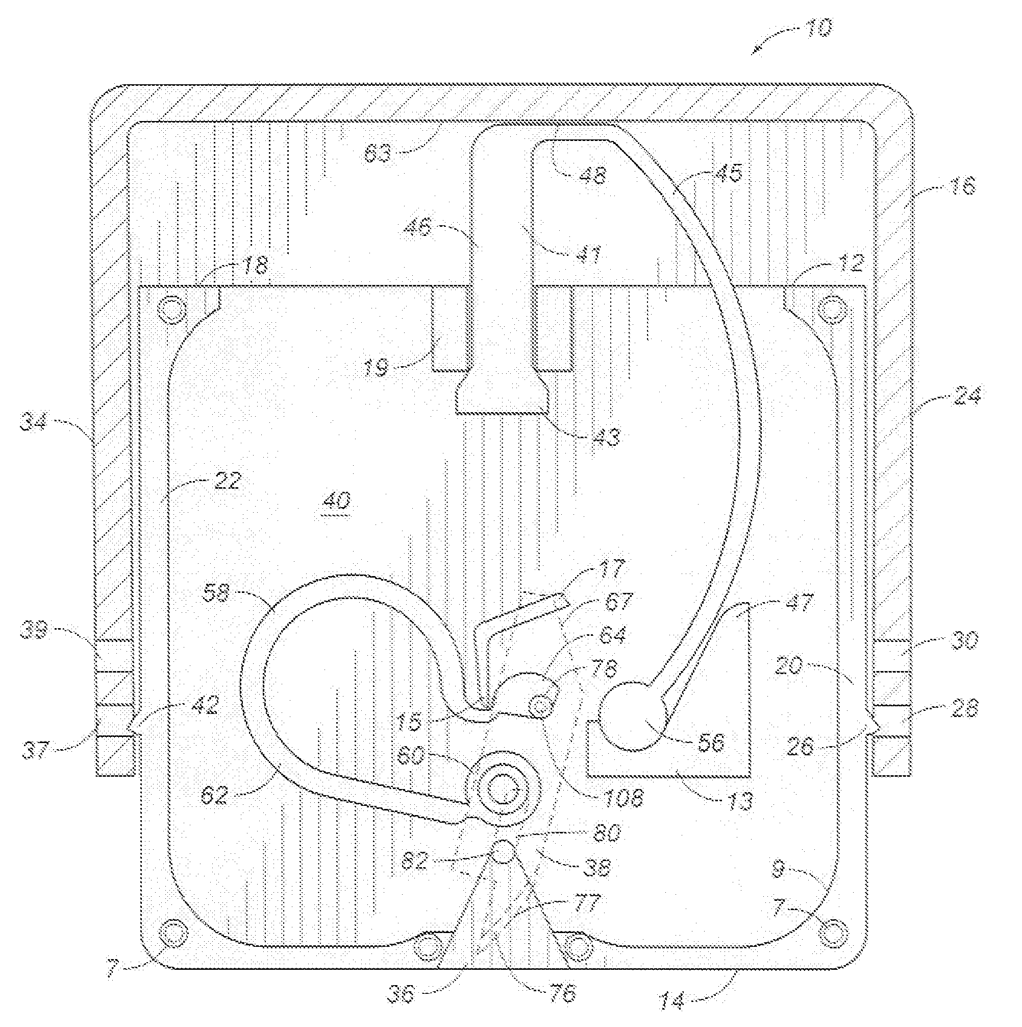
Figure 1 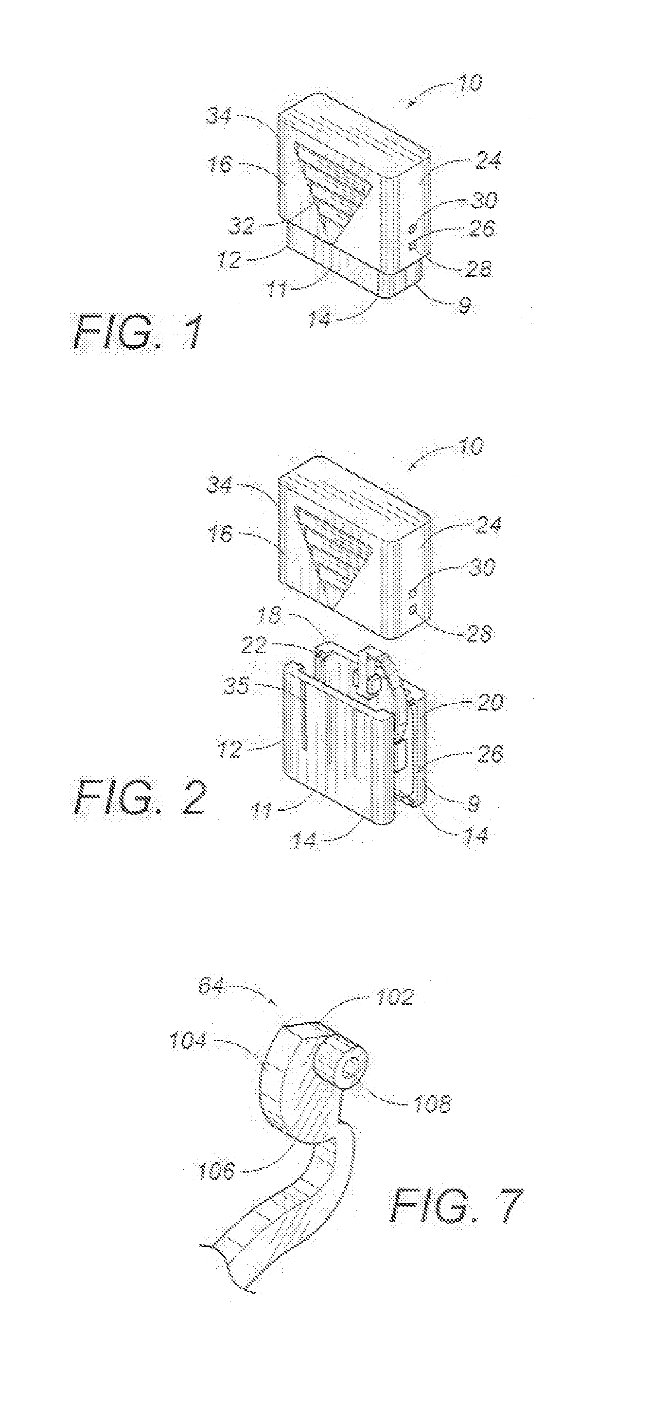
Figure 2 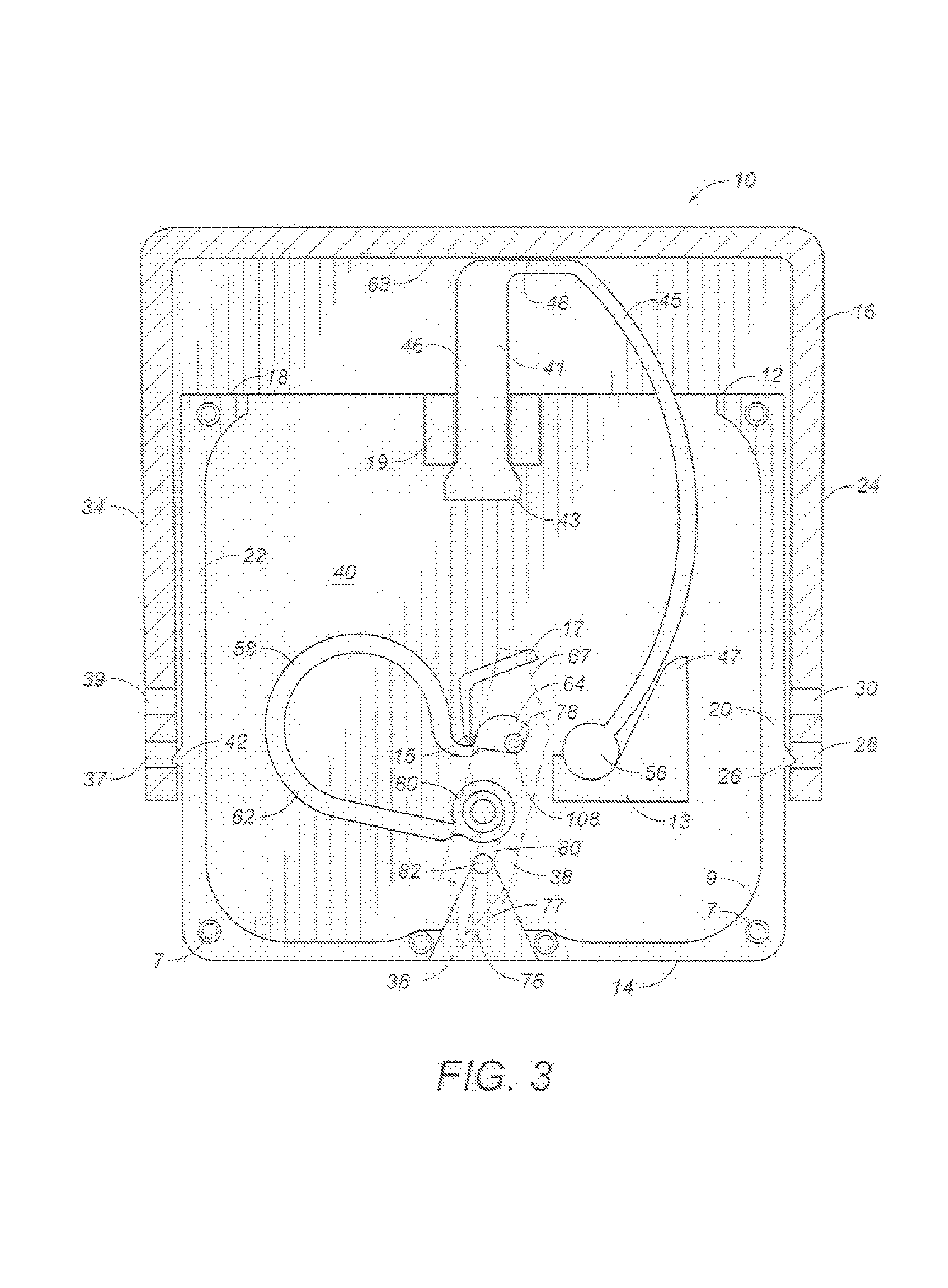
Figure 3
Abstract
Description
RELATED U.S. APPLICATIONS
[0001] The present application is a continuation-in-part application claiming priority from U.S. patent application Ser. No. 10 / 628,199, filed on Jul. 28, 2003, and entitled “LOAD-CONTROLLED AUTO-ACTUATED SKIN INCISION DEVICE”, presently pending.STATEMENT REGARDING FEDERALLY SPONSORED RESEARCH OR DEVELOPMENT
[0002] Not applicable.REFERENCE TO MICROFICHE APPENDIX
[0003] Not applicable.FIELD OF THE INVENTION
[0004] The present invention relates to medical devices. More particularly, the present invention relates to devices for incising the skin. In particular, the present invention relates to internal actuators for skin incising devices which apply a controlled load and a constant force during the incising operation for a patterned incision. Additionally, the present invention relates to skin incising devices that are used for the purpose of blood acquisition.BACKGROUND OF THE INVENTION
[0005] In the medical field, it is a very common procedure, and often very necessar...
Examples
Embodiment Construction
[0046]Referring to FIGS. 1 and 2, there is shown the skin incision device 10 in accordance with the teachings of the preferred embodiment of the present invention. The skin incision device 10 includes a casing 12 having a bottom surface 14 and a cover 16 slidably positioned on the casing 12. The top cover 16 is slidable in a direction transverse to a plane of the bottom surface 14. The casing 12 can have a first panel 9 and a second panel 11.
[0047]The casing 12 has a generally open end 18 opposite the bottom surface 14. The casing 12 has sides 20 and 22 extending upwardly from the bottom surface 14. The cover 16 extends over the open end 18 of the casing 12 and has a wall 24 extending over at least a portion of the side 20 of the casing 12. The side 20 has a barb 26 extending outwardly therefrom. The wall 24 has a first retaining slot 28 and second retaining slot 30 formed above the first retaining slot 28. As can be seen in FIG. 1, the barb 26 engages the first retaining slot 28.
[0...