
90-degree phase shifter
a phase shifter and 90 degree technology, applied in pulse manipulation, pulse modulation carrier system, pulse technique, etc., can solve the problems of deviating from 90 degree, affecting the way it is fed back, and not always yielding output signals with a phase difference of exactly 90 degr
Patent Information
- Authority / Receiving Office
- US · United States
- Patent Type
- Patents(United States)
- Current Assignee / Owner
- Publication Date
- 2008-03-11
- Estimated Expiration
- Not applicable · inactive patent
Smart Images
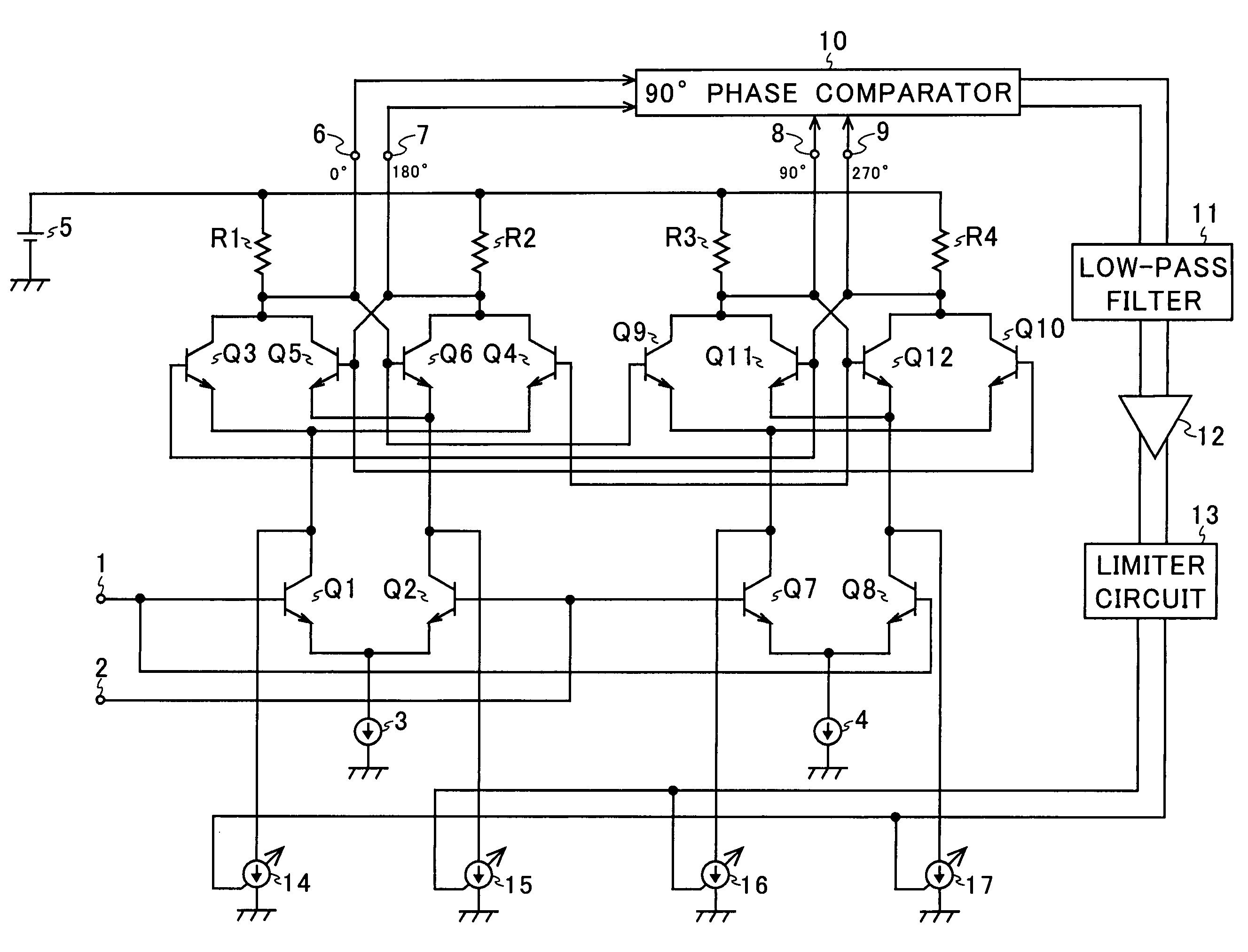
Figure 1 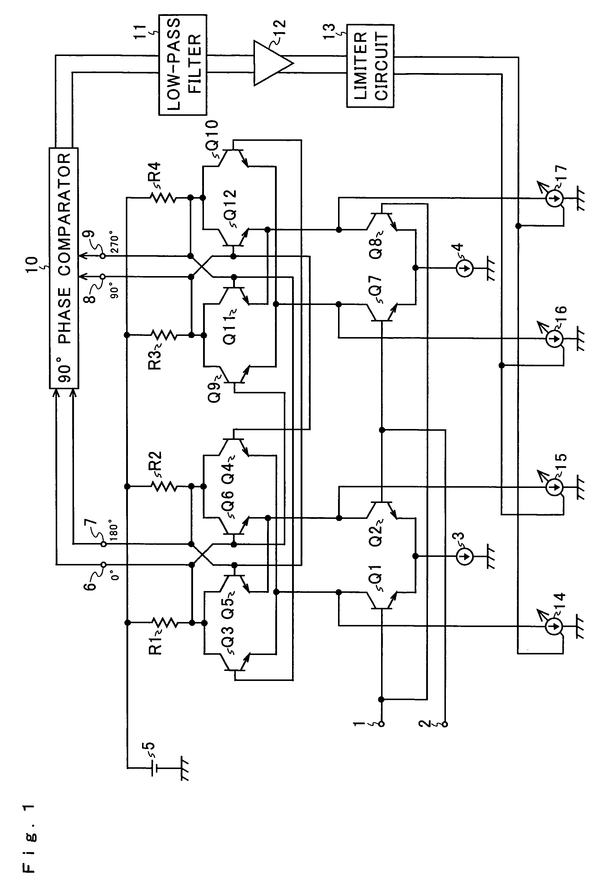
Figure 2 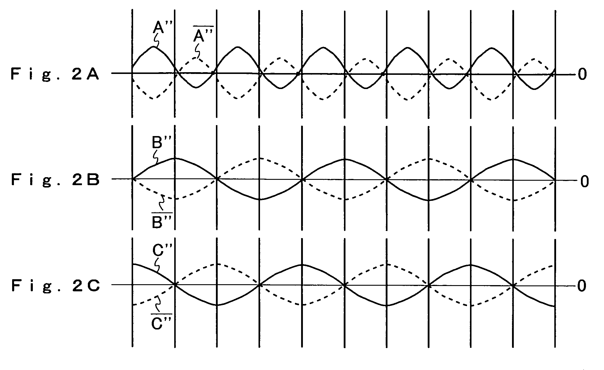
Figure 3
Abstract
Description
[0001] This nonprovisional application claims priority under 35 U.S.C. § 119(a) on Patent Application No. 2003-413635 filed in Japan on Dec. 11, 2003, the entire contents of which are hereby incorporated by reference.BACKGROUND OF THE INVENTION
[0002] 1. Field of the Invention
[0003] The present invention relates to a 90-degree phase shifter, and more particularly to a 90-degree phase shifter that is built using a T flip-flop.
[0004] 2. Description of Related Art
[0005] An example of the configuration of a conventional 90-degree phase shifter is shown in FIG. 3. The conventional 90-degree phase shifter shown in FIG. 3 is a 90-degree phase shifter built using a T flip-flop, and is composed of transistors Q1 to Q12, resistors R1 to R4, input terminals 1 and 2, constant current sources 3 and 4, a constant voltage source 5, and output terminals 6 to 9.
[0006] When an input signal having a predetermine frequency and having a duty factor of 50% is fed in via the input terminal 1, the input transisto...
Examples
Embodiment Construction
[0037]Hereinafter, an embodiment of the present invention will be described with reference to the accompanying drawings. An example of the configuration of a 90-degree phase shifter according to the invention is shown in FIG. 1. In FIG. 1, such circuit elements as find their counterparts in FIG. 6 are identified with common reference numerals or symbols.
[0038]As compared with the conventional 90-degree phase shifter shown in FIG. 3, the 90-degree phase shifter according to the invention shown in FIG. 1 is additionally provided with a 90-degree phase comparator 10, a low-pass filter 11, a DC amplifier 12, a limiter circuit 13, and variable current sources 14 to 17.
[0039]NPN-type transistors Q1 to Q12, input terminals 1 and 2, constant current sources 3 and 4, resistors R1 to R4, a constant voltage source 5, and output terminals 6 to 9 together constitute a T flip-flop that functions as a ½ frequency divider. The input terminal 1 is connected to the base of the input transistor Q1 and...