
Mop strainer
a strainer and mop technology, applied in carpet cleaners, lighting and heating apparatus, separation processes, etc., can solve the problems of affecting the safety of workers, the risk of life-threatening, and the difficulty of repeating the operation, so as to prevent the mop from falling down and facilitate the effect of repeated operation
Patent Information
- Authority / Receiving Office
- US · United States
- Patent Type
- Patents(United States)
- Current Assignee / Owner
- Publication Date
- 2012-08-14
- Estimated Expiration
- Not applicable · inactive patent
Smart Images
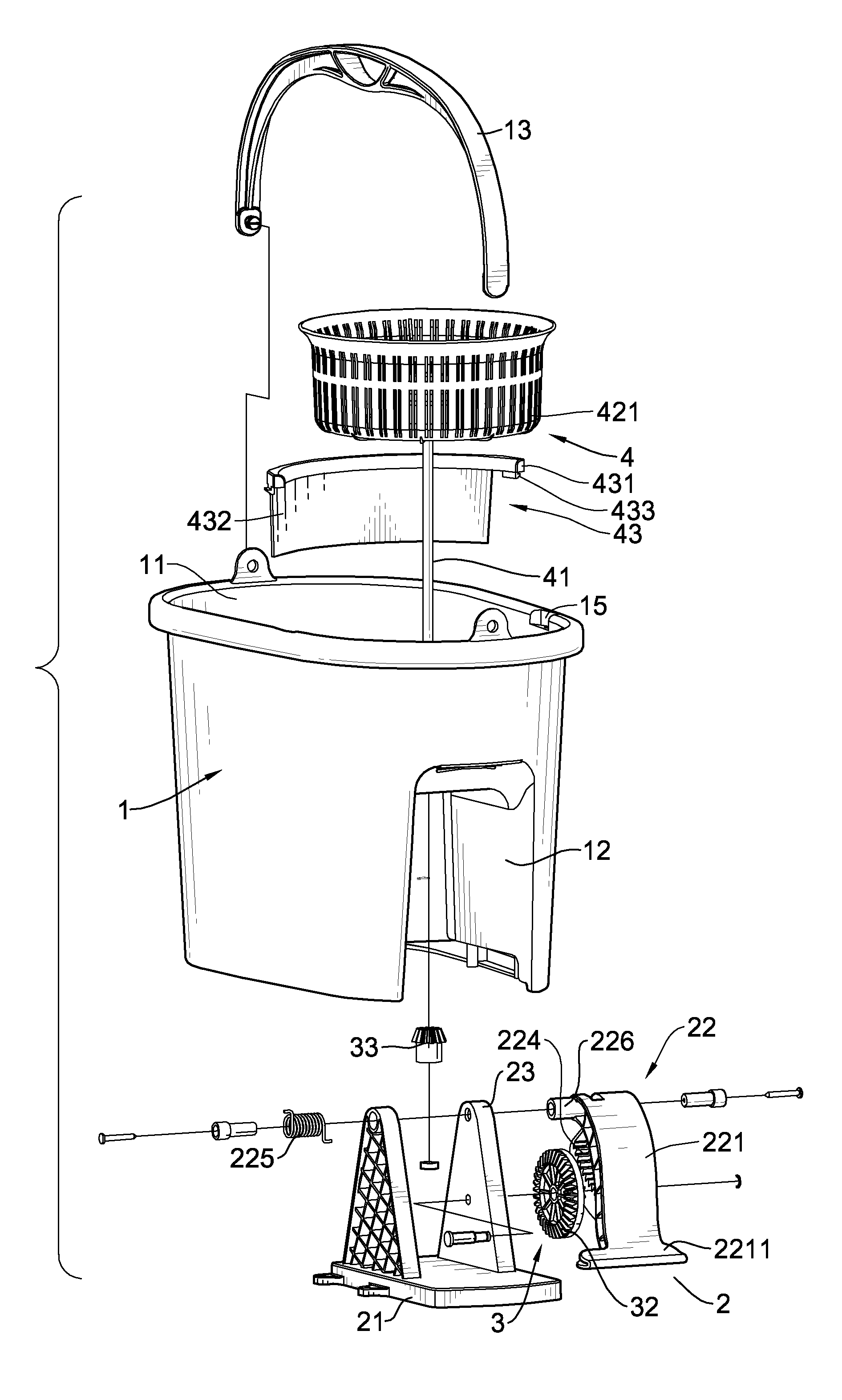
Figure 1 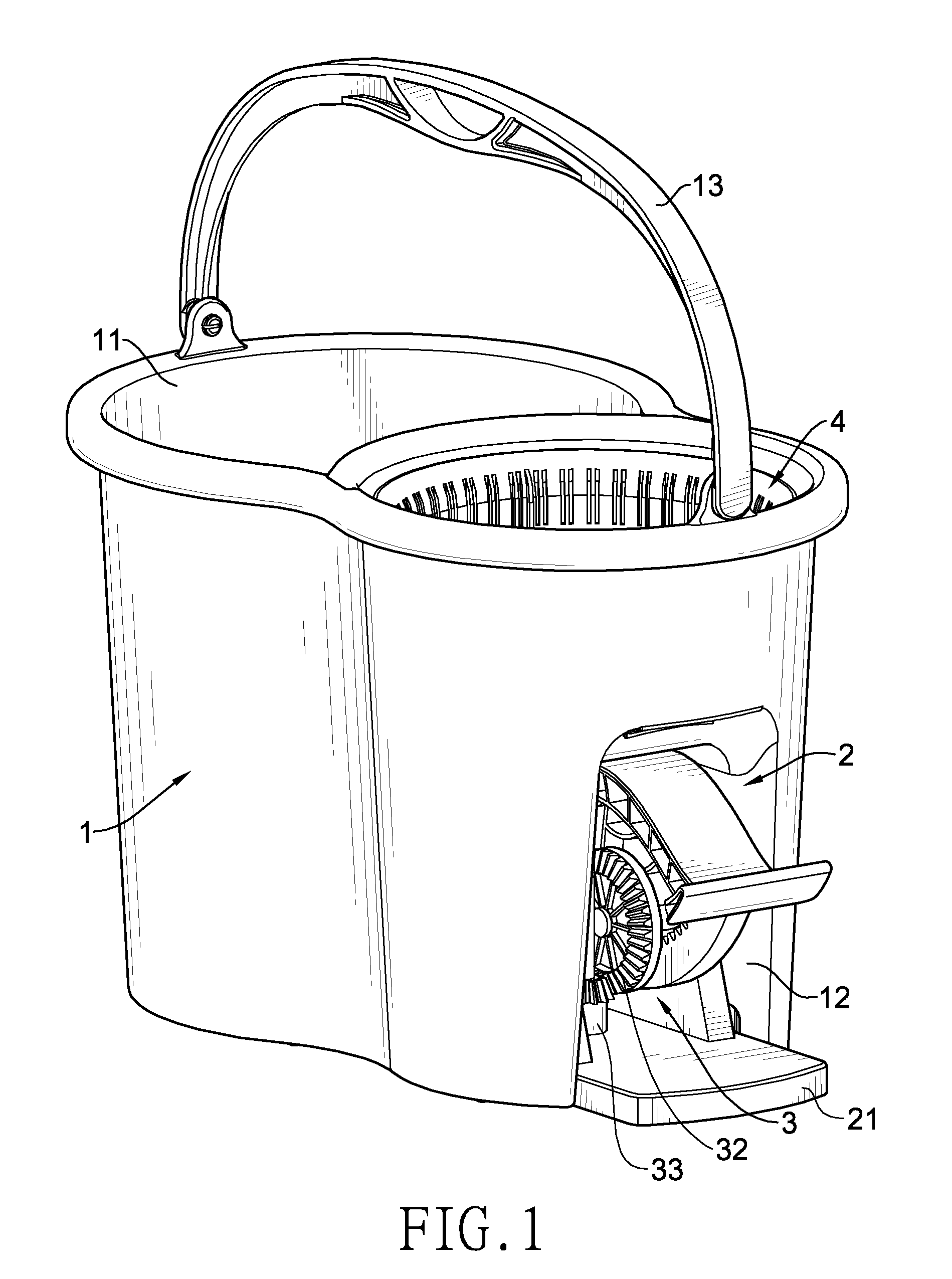
Figure 2 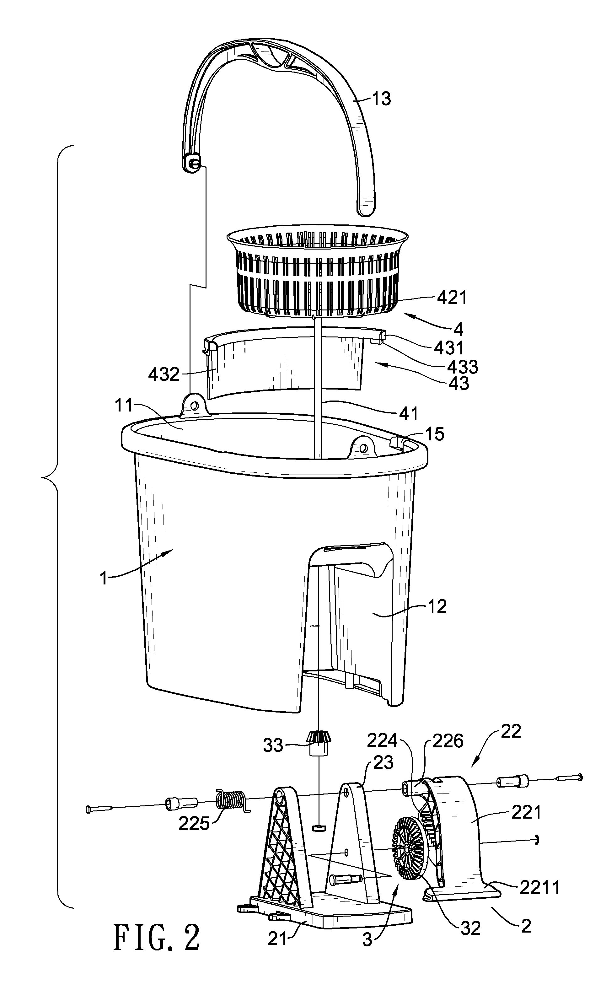
Figure 3
Abstract
Description
BACKGROUND OF THE INVENTION
[0001] 1. Field of the Invention
[0002] The present invention is related to a mop strainer, and more particularly to a mop strainer extracting water with centrifugal force.
[0003] 2. Description of the Related Art
[0004] Draining a mop is a painstaking job. If a mop is not fully drained, a floor mopped thereby could be left wet and slippery. People walking on a wet floor may easily slip and fall, sometimes, such risk may be life-threatening.
[0005] To improve draining efficiency, a conventional pail for a mop has a bucket, a driving unit, a transmission unit and a draining unit. The bucket has a chamber for receiving the driving unit. The driving unit has a base fixedly mounted on the bucket. A movable member pivotally reciprocating and a transmission member controlled by the movable member are mounted on the base. A pedal is formed on one side of the movable member for a user to step on. An arced rack is stretched over a rear surface of the pedal, and a free end o...
Examples
Embodiment Construction
[0022]With reference to FIGS. 1 to 3, a mop strainer of the present invention has a bucket (1), a driving unit (2), a transmission unit (3) and a draining unit (4).
[0023]The bucket (1) is used to contain the water drained from a mop and has a chamber (11), a pedal mount (12), a handle (13), a bottom board (14) and two recesses (15).
[0024]The chamber (11) is defined in the bucket (1) and serves to accommodate water. The pedal mount (12) is a recess formed into the bucket (1) for receiving the driving unit (2), the transmission unit (3) and a part of the draining unit (4). The handle (13) has two ends pivotally mounted on a top edge of the bucket (1) for lifting the bucket (1). The bottom board (14) is a bottom of the bucket (1) and has an uneven portion (141) and a raised portion (142). With reference to FIG. 6, the raised portion (142) is raised above the uneven portion (141) and is located directly above the pedal mount (12). Multiple parallel ribs (143) are formed on the uneven po...