
Rifle
a technology of rifles and hammers, applied in the field of rifles, can solve the problems of prone to defects and rather complex design of rifles, and achieve the effects of strong anchorage, strong fore-end structure, and simple and effective manufacturing
Patent Information
- Authority / Receiving Office
- US · United States
- Patent Type
- Patents(United States)
- Current Assignee / Owner
- Publication Date
- 2010-03-30
- Estimated Expiration
- Not applicable · inactive patent
Smart Images
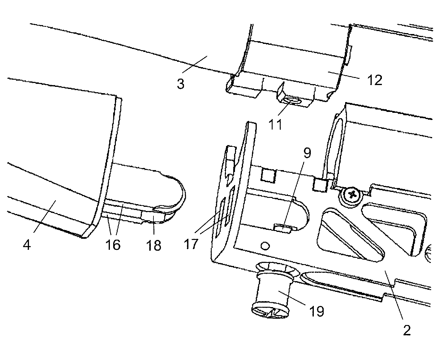
Figure 1 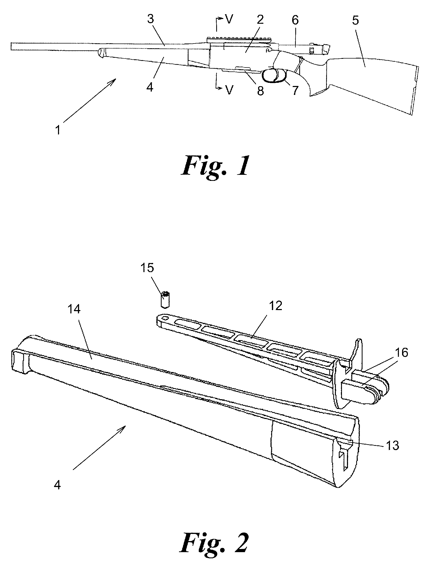
Figure 2 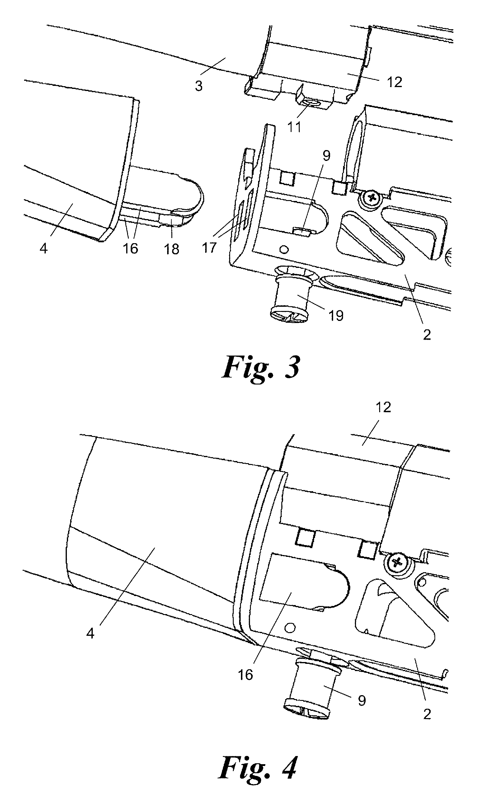
Figure 3
Abstract
Description
BACKGROUND OF THE INVENTION
[0001] The present invention relates to a rifle having a housing, a barrel anchored on it and a fore-end extending under the barrel, in which case the barrel can be anchored with the aid of an attachment means which passes through a lateral hole in the housing, and the fore-end has at least one axial projection which engages detachably in a holder in the housing.
[0002] Rifles with an interchangeable fore-end allow different fore-ends to be used for different purposes, for example one fore-end with a bipod which can be unfolded for sniper use, a slim fore-end for hunting use, etc.
[0003] It is known, for detachable attachment of the fore-end for the axial projection to be equipped with sprung latching tabs which can be pulled back by a mechanism inside the fore-end in order to hold the fore-end. This design is rather complex to manufacture and is susceptible to defects during use.
[0004] The invention is based on the object of providing a simple, safe and reliabl...
Examples
Embodiment Construction
[0016]FIG. 1 shows a rifle 1 with a housing 2, a barrel 3, a fore-end 4 which extends under the barrel 3, and a conventional rear stock 5. The housing 2 holds a breech 6, a trigger device 7 and a magazine 8, and produces the force connection between all the components, as is known from the prior art. The housing 2 may comprise a central mount and side stock pieces 2′ (FIGS. 1 and 5).
[0017]As shown in FIGS. 3 to 5, the barrel 3 is detachably anchored on the housing 2 by means of an attachment means in the form of a screw 9. For this purpose, the screw 9 passes through a vertical lateral hole 10 in the housing 2 and engages in a corresponding thread 11 in the root 12 of the barrel 3.
[0018]FIG. 2 shows a detail view of the design of the fore-end 4. The fore-end 4 has an inner mount 12 composed of plastic or metal, for example aluminum. The inner mount 12 is pushed into an axial groove 13 in a surrounding grip part 14, for example composed of plastic or wood, where it is fixed axially w...