
Roof line light holder
a technology for roof lines and light holders, which is applied in the direction of electric lighting, lighting and heating equipment, lighting support devices, etc., can solve the problems of unsuitable annual installation for light hanging use, and shingle tab and gutter hooks often undesired to lack structural rigidity. , to achieve the effect of enhancing the structural rigidity of the holder, enhancing the frictional characteristics of the surfa
Patent Information
- Authority / Receiving Office
- US · United States
- Patent Type
- Patents(United States)
- Current Assignee / Owner
- Publication Date
- 2012-11-20
Smart Images
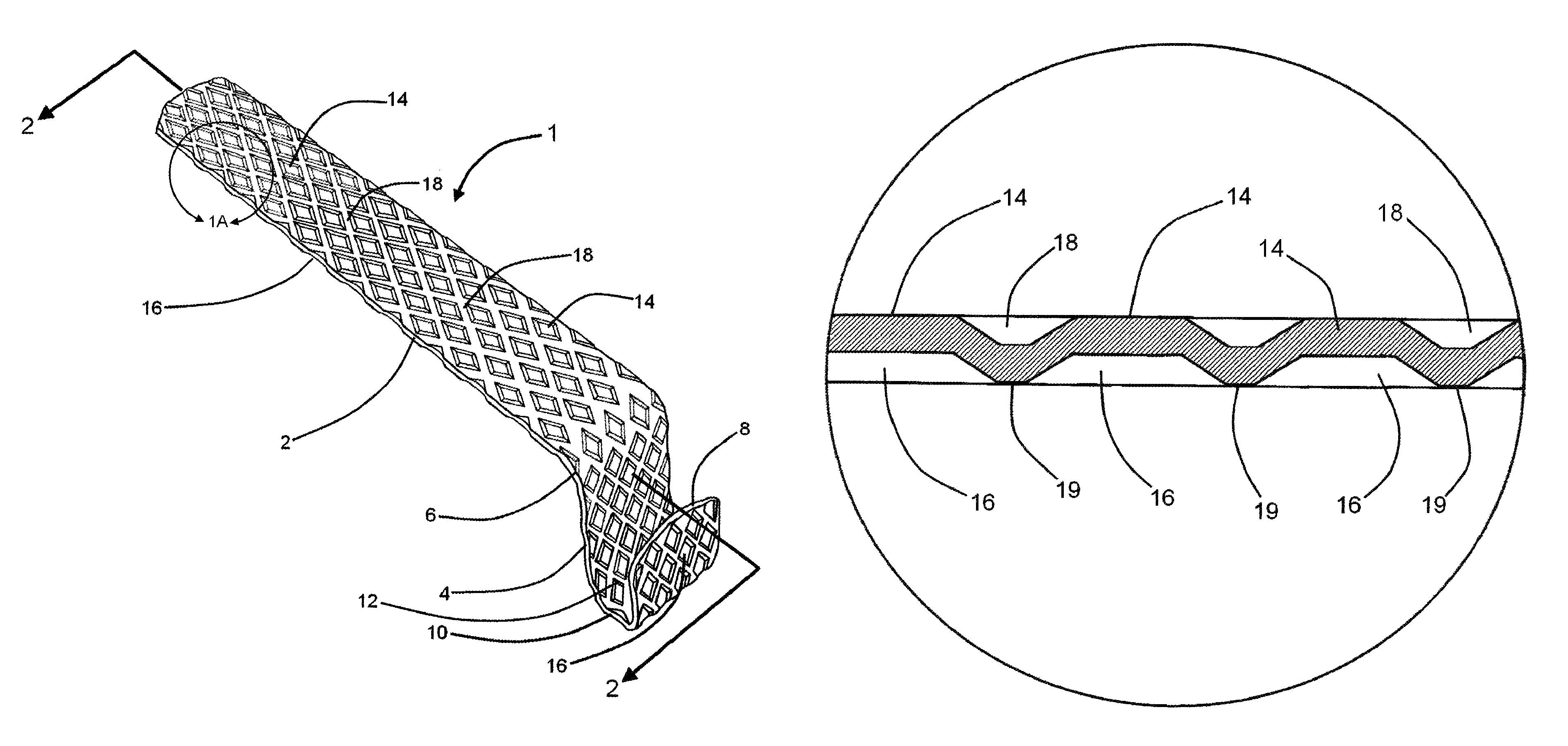
Figure 1 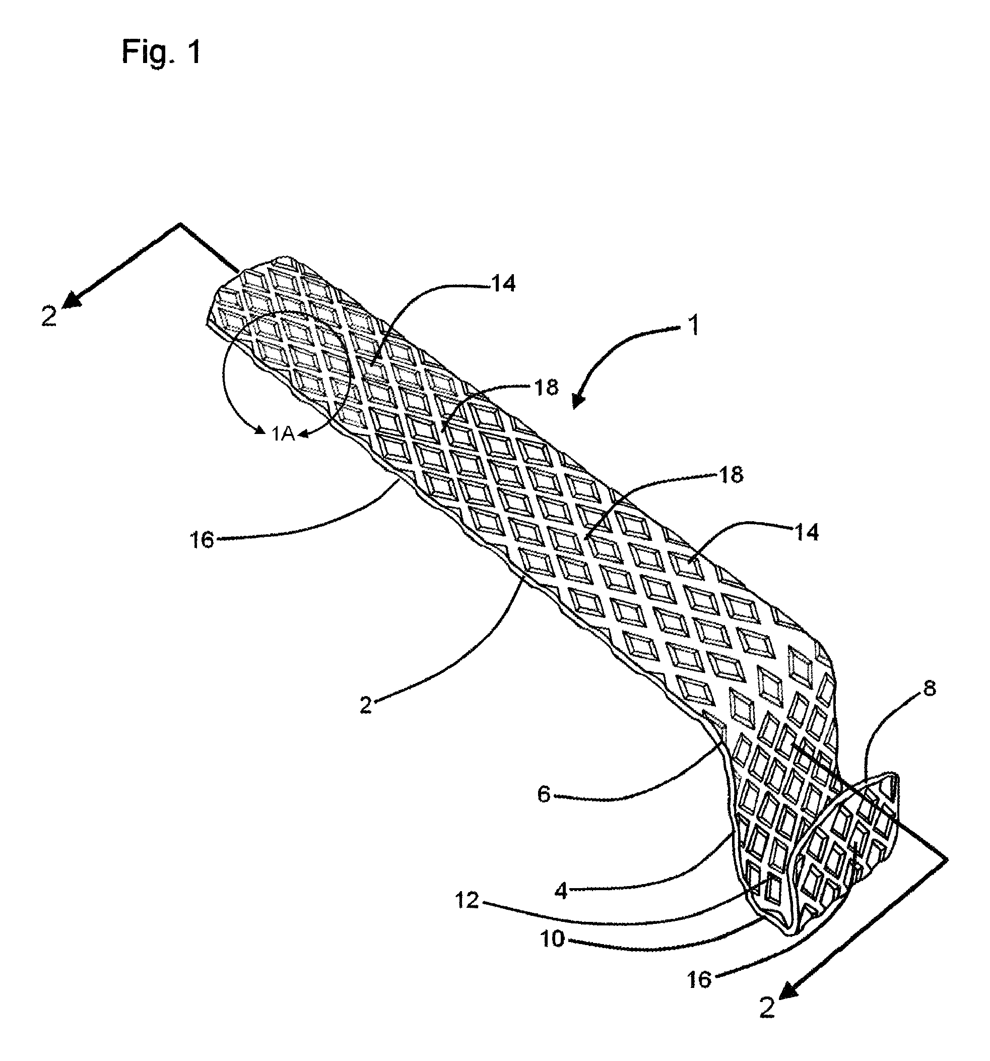
Figure 2 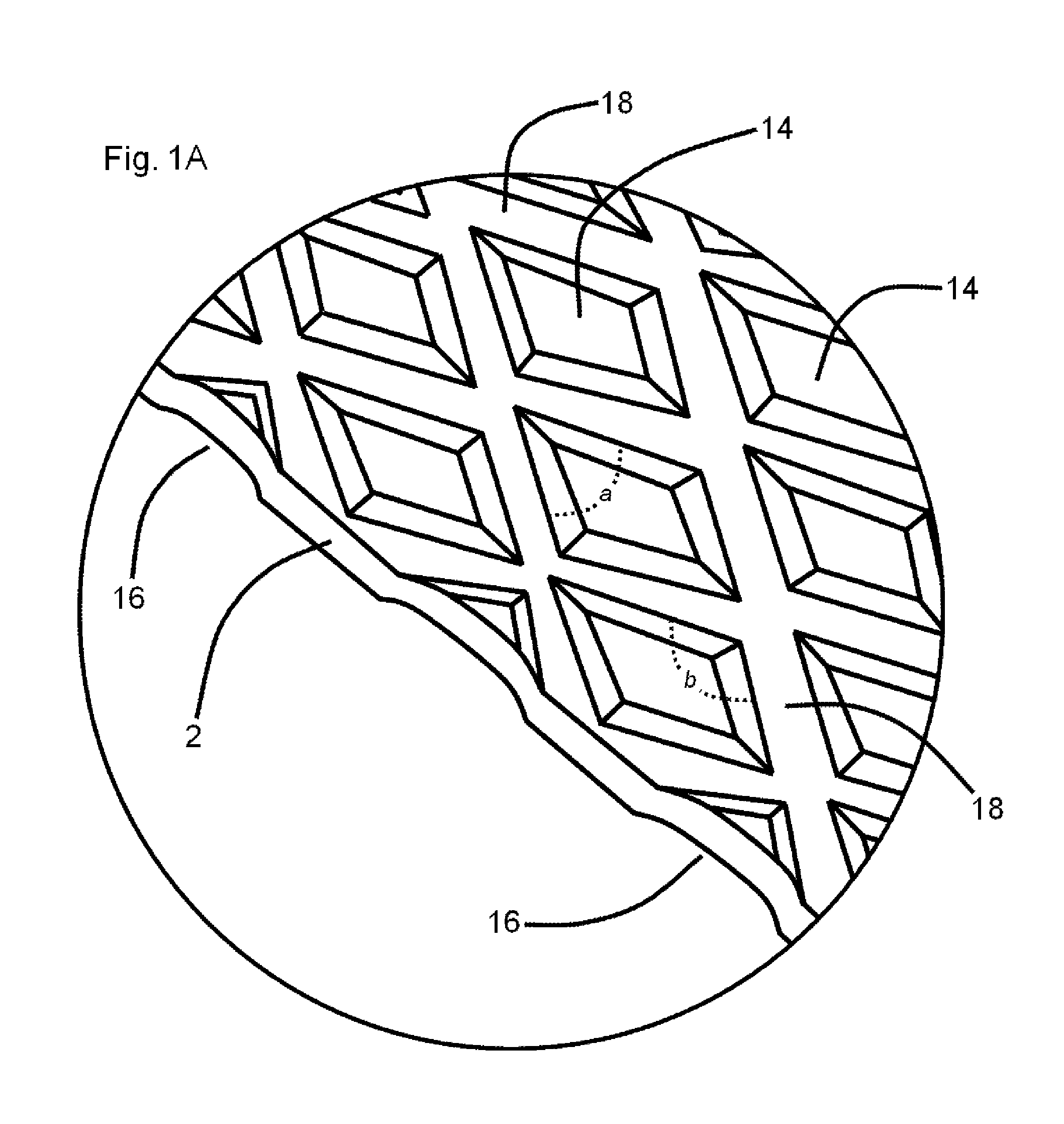
Figure 3
Abstract
Description
FIELD OF THE INVENTION
[0001] This invention is related to hooks, brackets and clips which are adapted for mounting and holding decorative holiday electrical string lighting, such as electrical Christmas lights, at and along the roof lines of residential and commercial buildings.
[0002] More particularly, the instant invention is related to such hooks, brackets and clips which include specialized surface features adapted to enhance their durability and usability.BACKGROUND OF THE INVENTION
[0003] During winter holiday seasons, strings of decorative electrical lights are traditionally mounted and hung along the eves of residential and commercial buildings. In order to facilitate such traditional practice, shingle tab hooks and gutter hooks are known to be utilized. Such tabs and hooks commonly present a longitudinally extending wire hooking structure, and such tabs and hooks are typically composed of flexible plastic.
[0004] Such known shingle tab hooks and gutter hooks often undesirably fai...
Examples
Embodiment Construction
[0021]Referring now to the drawings, and in particular to Drawing FIG. 1, a preferred embodiment of the instant inventive roof line light holder is referred to generally by Reference Arrow 1. The roof line light holder 1 has a suspension tie section 4, a friction arm section 2, and a wire cradle 8,10. Preferably, the upper end of the suspension tie section 4 is attached by whole or continuous formation to the forward or longitudinal end of the friction arm 2, such connection preferably being configured as a downwardly curving transition section 6. The wire cradle section 8,10 is preferably similarly wholly formed with the lower end of the suspension tie 4, the wire cradle 8,10 forming and defining an upwardly opening wire receiving and retaining space 12.
[0022]Referring simultaneously to FIGS. 1 and 1A, a multiplicity of knurls 14 preferably extend from the friction arm 2. Such multiplicity of knurls 14 preferably further includes knurls extending from the transition section 6, from...