
Acoustic structure
a technology of acoustic structure and acoustic cylinder, which is applied in the field of acoustic structure, can solve problems such as adjusting bandwidth
Patent Information
- Authority / Receiving Office
- US · United States
- Patent Type
- Patents(United States)
- Current Assignee / Owner
- Publication Date
- 2014-05-06
- Estimated Expiration
- Not applicable · inactive patent
Smart Images
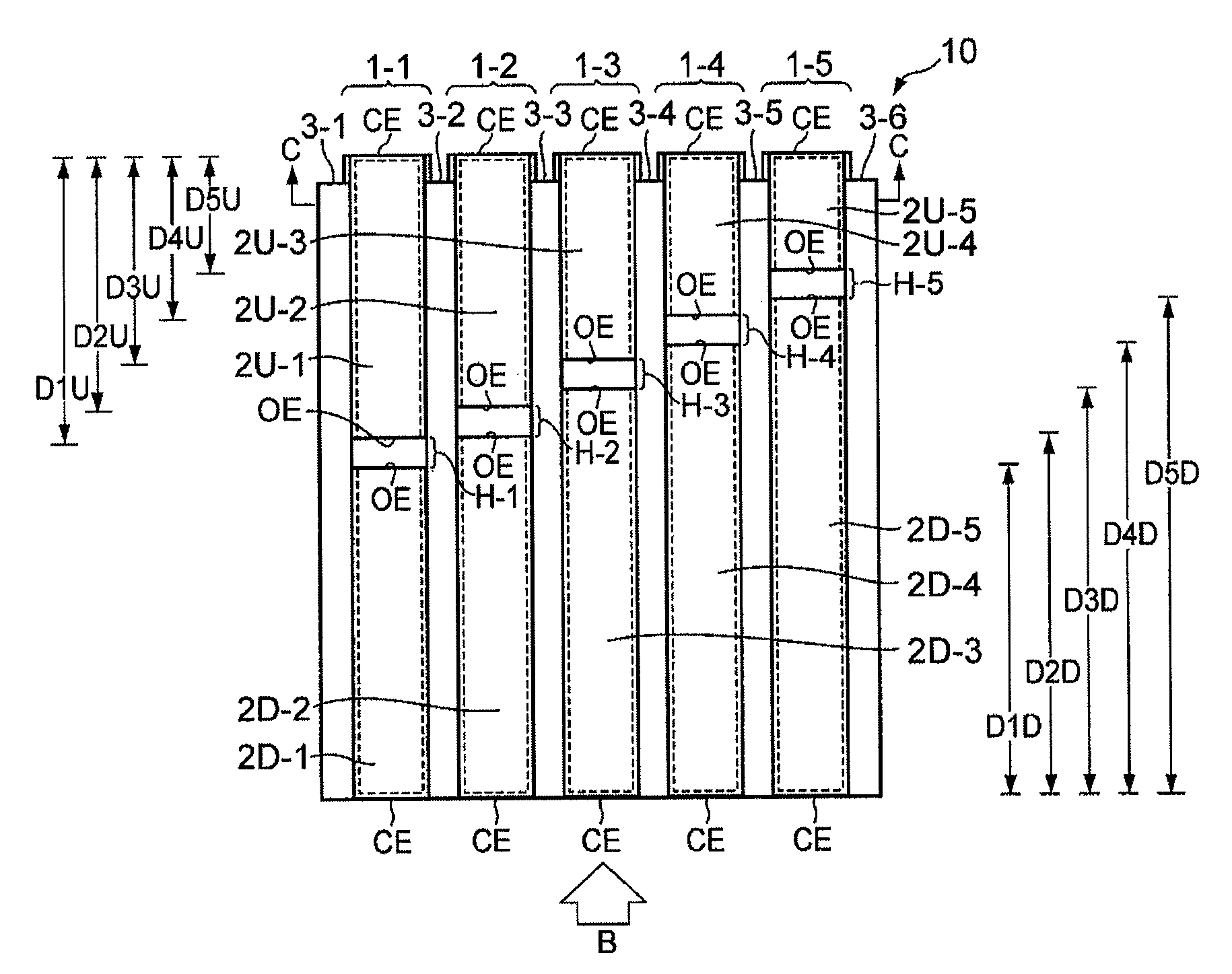
Figure 1 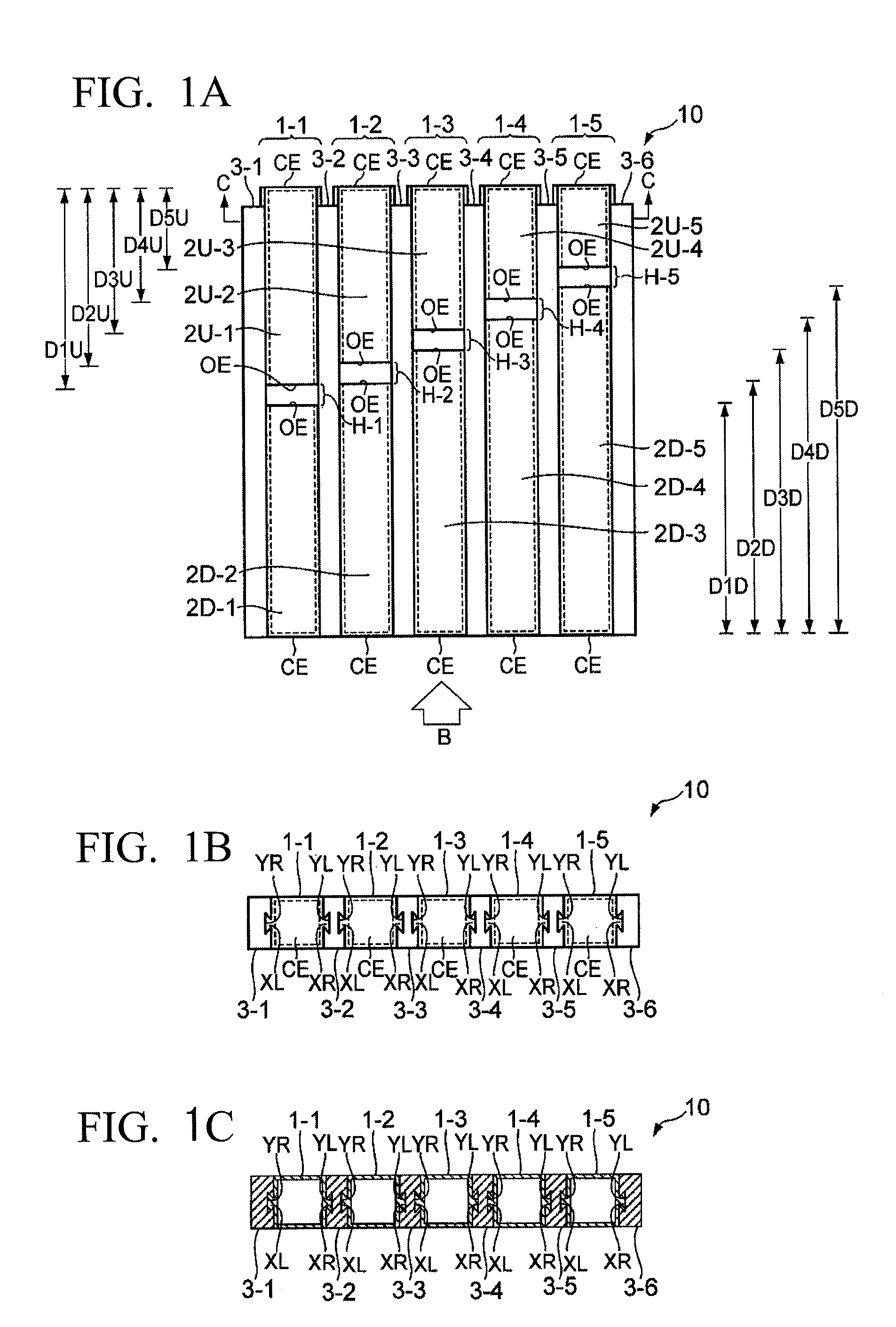
Figure 2 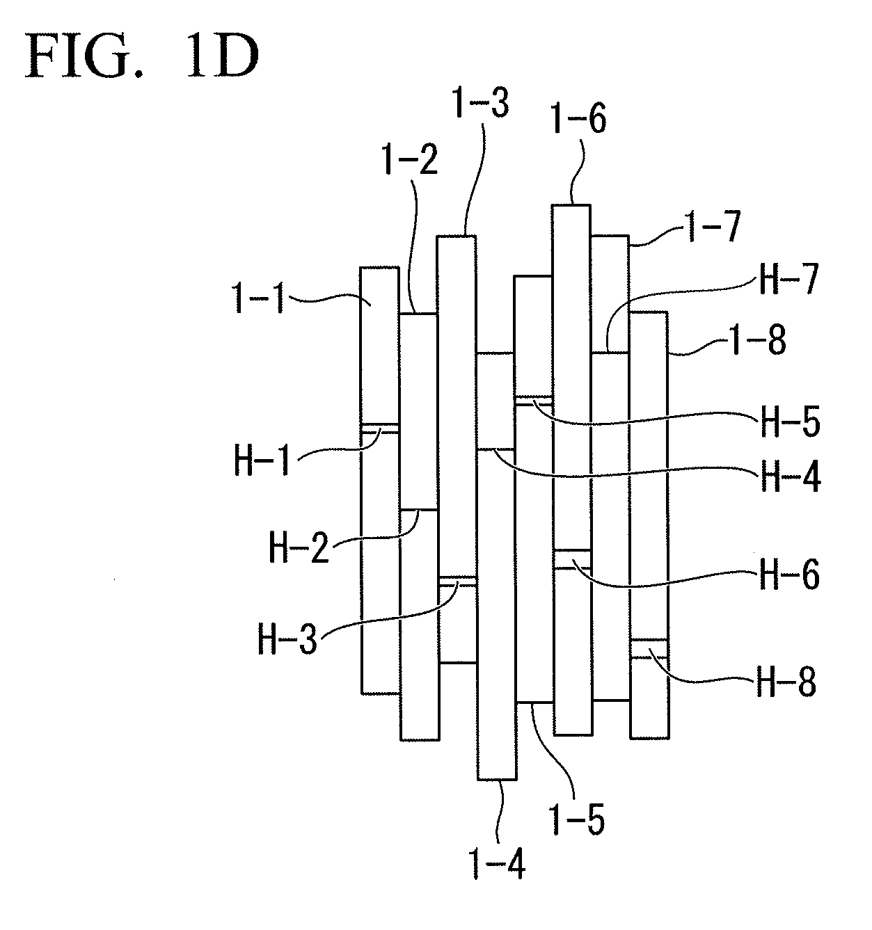
Figure 3
Abstract
Description
BACKGROUND OF THE INVENTION
[0001] 1. Field of the Invention
[0002] The present invention relates to an acoustic structure that is able to produce a sound-absorbing effect and a sound-scattering effect, thus preventing acoustic disturbance / trouble in an acoustic space.
[0003] The present application claims priority on Japanese Patent Application No. 2011-254633 filed Nov. 22, 2011, the entire content of which is incorporated herein by reference.
[0004] 2. Description of the Related Art
[0005] It is known that an acoustic structure including a plurality of pipes (or resonance tubes) having openings at their surfaces may produce a sound-absorbing effect and a sound-scattering effect via pipes so as to prevent acoustic disturbance / trouble (e.g. flutter echo) in an acoustic space (e.g. a sound chamber). FIG. 6 shows a conventional example of an acoustic structure 90 including five pipes 25-m (where m=1 to 5) having the same length, which are horizontally aligned in a direction perpendicular to th...
Examples
first embodiment
1. First Embodiment
[0041]FIG. 1A is a front view of an acoustic structure 10 according to a first embodiment of the present invention. FIG. 1B is a side view of the acoustic structure 10 viewed in a direction B. FIG. 1C is a cross-sectional view taken along line C-C in FIG. 1A. As shown in FIGS. 1A to 1C, the acoustic structure 10 includes five resonance tubes 1-i (where i=1 to 5) and six boards 3-i (where i=1 to 6). In the acoustic structure 10, the resonance tube 1-i includes an internal cavity encompassed by side faces, one of which is equipped with an opening. The acoustic structure 10 is designed to manually adjust the opening area of the resonance tube 1-i. The resonance tube 1-i is divided into two tubes 2U-i, 2D-i (where i=1 to 5) each having an open end OE. Each of the tubes 2U-i, 2D-i has a prismatic shape with an open end OE and a closed end CE. The length of the tube 2U-i and the length of the tube 2D-i are differentiated depending on the resonance tube 1-i, but the sum ...
second embodiment
2. Second Embodiment
[0050]FIG. 2A is a front view of an acoustic structure 10A according to a second embodiment of the present invention. FIG. 2B is a side view of the acoustic structure 10A viewed in a direction B in FIG. 2A. FIG. 2C is a cross-sectional view taken along line C-C in FIG. 2A. In FIGS. 2A, 2B, 2C, parts identical to those shown in FIGS. 1A, 1B, 1C are denoted using the same reference signs. For the sake of convenience, FIG. 2B does not include the reference signs of the projections XL, XR and the recesses YL, YR. Compared to the acoustic structure 10 shown in FIGS. 1A-1C, the acoustic structure 10A shown in FIGS. 2A-2C are equipped with a plurality of sheet members 4-i (where i=1 to 5) and a plurality of support members 5L-i, 5R- (where i=1 to 5). The sheet member 4-i is a movable adjuster for shielding the hole H-i, which is formed between the open ends OE of the tubes 2U-i, 2D-i facing each other. The support member 5L-i, 5R-i support the sheet member 4-i to freely...
third embodiment
3. Third Embodiment
[0054]FIG. 3A is a front view of an acoustic structure 10B according to a third embodiment of the present invention. FIG. 3B is a side view of the acoustic structure 10A viewed in a direction B in FIG. 3A. FIG. 3C is a cross-sectional view taken along line C-C in FIG. 3A. The acoustic structure 10B includes five resonance tubes 6-j (where j=1 to 5) and four pairs of boards 8U-j, 8D-j (where j=1 to 4) which are vertically aligned to adjoin each other. Herein, a pair of boards 8U-j, 8D-j is held between a pair of resonance tubes 6-j, 6j+1 which are horizontally aligned to adjoin each other. In the acoustic structure 10B, the resonance tube 6-j has three pairs of side faces positioned opposite to each other, i.e. a pair of side faces UW, DW, a pair of side faces FW, BW, and a pair of side faces LW, RW. For the sake of convenience, FIG. 3A does not include the reference signs UW, DW, FW, BW, LW, RW with regard to the resonance tubes 6-2 to 6-5 except for the resonance...