
Friction stir welding apparatus
a technology of friction stir and welding apparatus, which is applied in welding apparatus, metal-working apparatus, manufacturing tools, etc., can solve the problems of not knowing the size of the probe to be used, not knowing the cleaning method with respect to the rotatable probe, etc., and achieves the effect of reliable detection, simple configuration and reliable detection
Patent Information
- Authority / Receiving Office
- US · United States
- Patent Type
- Patents(United States)
- Current Assignee / Owner
- Publication Date
- 2016-02-02
Smart Images
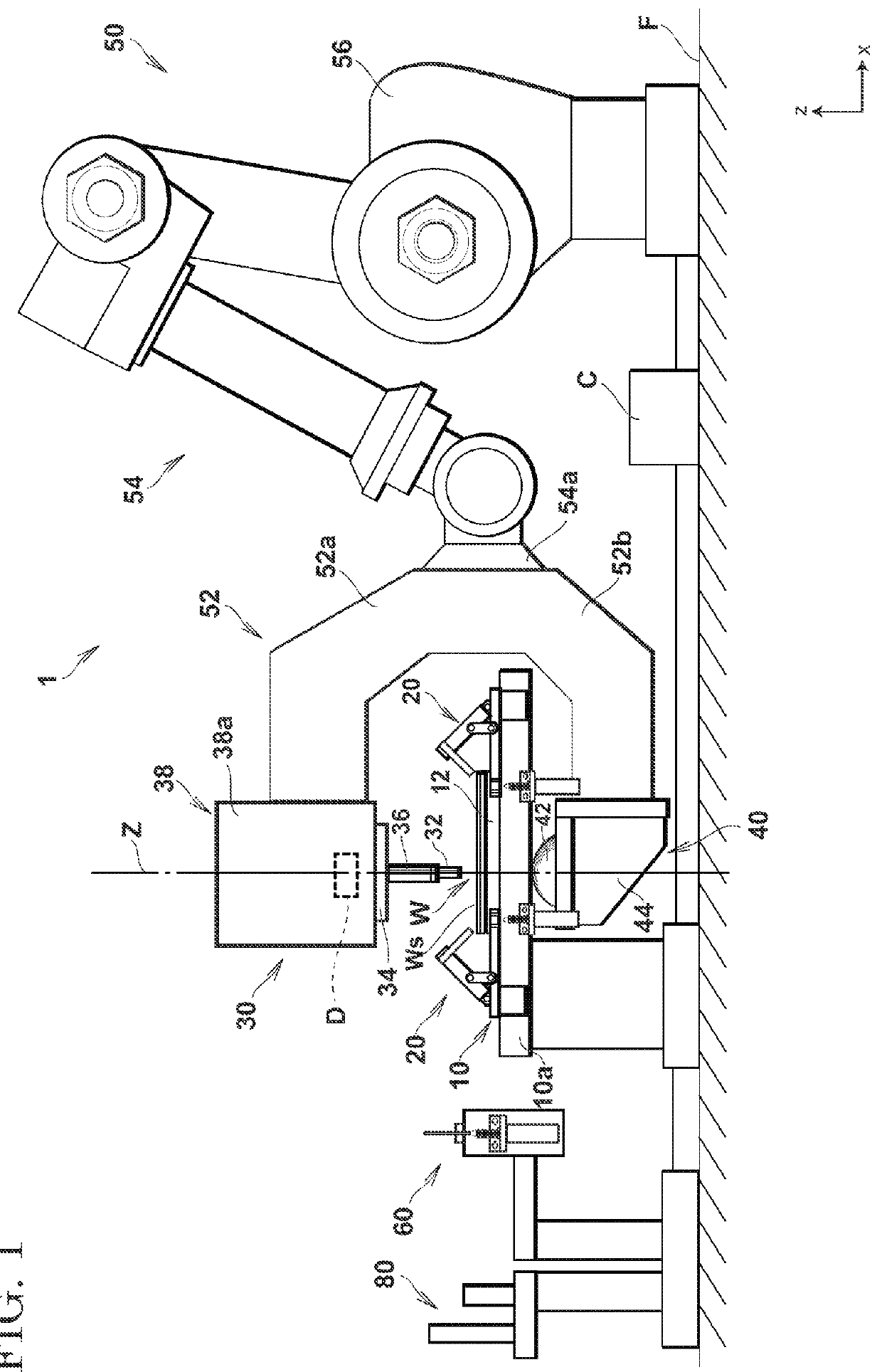
Figure 1 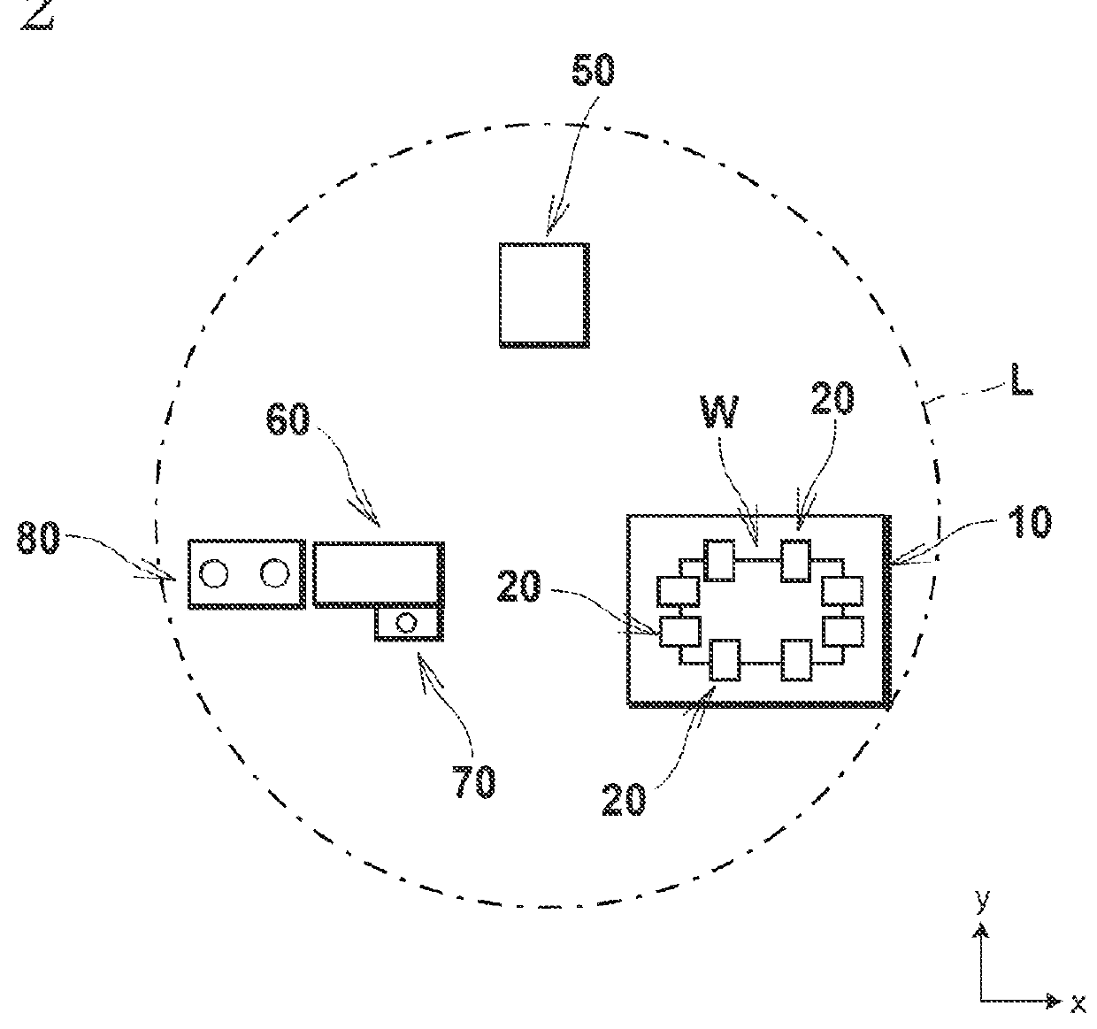
Figure 2 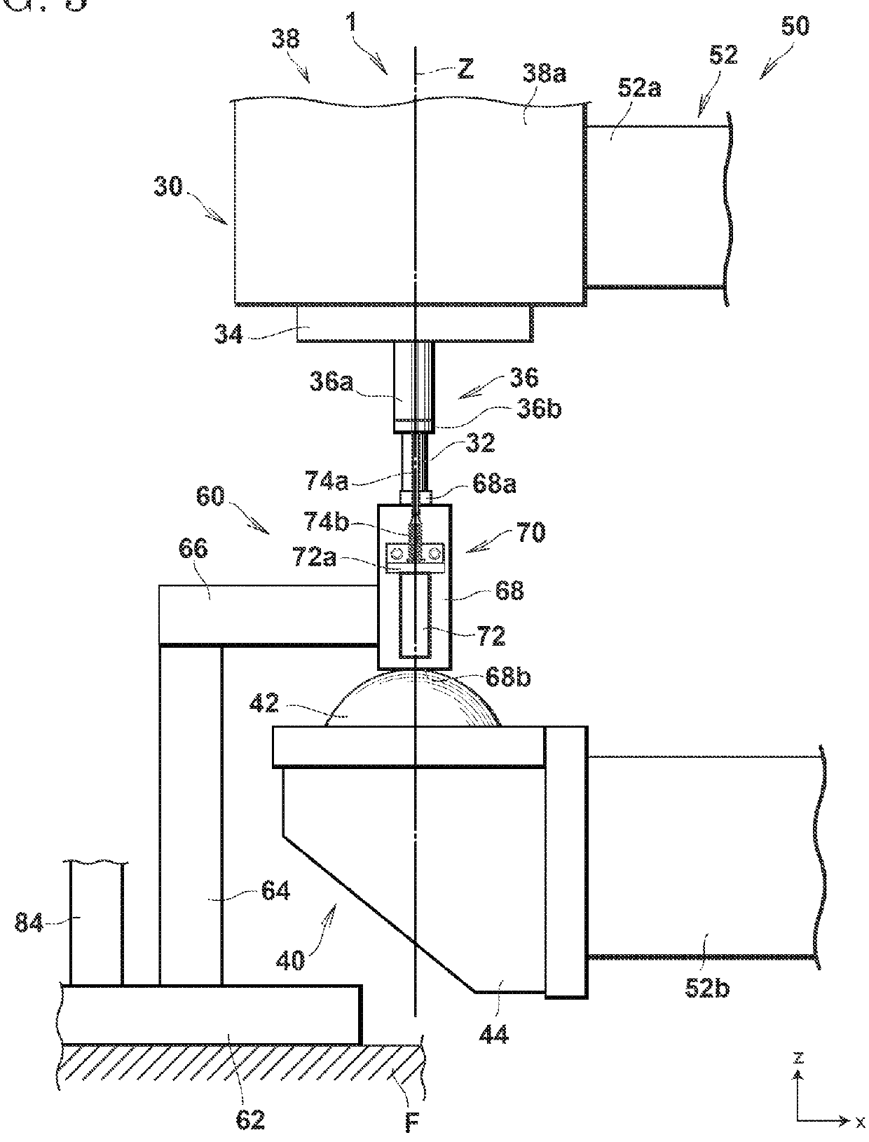
Figure 3
Abstract
Description
BACKGROUND OF THE INVENTION
[0001] The present invention relates to a friction stir welding apparatus, and more particularly relates to a friction stir welding apparatus having a probe detection mechanism, a processing-member detection mechanism, and a probe cleaning mechanism.
[0002] In recent years, there has been proposed a friction stir welding apparatus that performs friction stirring on a predetermined welding portion in a processing target component formed by a plurality of metal plates such as aluminum plates by a probe rotating at a high speed, in addition to general arc welding, to weld the metal plates with each other. Even in a strength component of a movable body such as an automobile, a configuration having a welding portion welded by a friction stir welding apparatus has been realized.
[0003] In such a friction stir welding apparatus, the rotating probe and the processing target component need to be moved relative to each other to weld a predetermined welding portion accura...
Examples
Embodiment Construction
[0041]A friction stir welding apparatus according to an embodiment of the present invention is explained in detail below with reference to the accompanying drawings. In the drawings, an x-axis, a y-axis, and a z-axis constitute a three-axis orthogonal coordinate system. A plane defined by the x-axis and the y-axis is parallel to a horizontal plane, and a normal direction of the z-axis is an upward direction.
[0042]A configuration of the friction stir welding apparatus according to the present embodiment is explained in detail with reference to FIGS. 1 to 7.
[0043]FIG. 1 is a side view showing an overall configuration of the friction stir welding apparatus according to the present embodiment. FIG. 2 is a schematic top view showing an arrangement range of respective constituent elements of the friction stir welding apparatus according to the present embodiment. FIG. 3 is a partial enlarged side view showing a probe detection mechanism of the friction stir welding apparatus according to ...