
Method for producing a directional layer by cathode sputtering, and device for implementing the method
a directional layer and cathode sputtering technology, applied in the direction of electrolysis components, vacuum evaporation coatings, coatings, etc., can solve the problems of insatiable solution for all applications, too limited substrate size and shape to yield acceptable results, etc., to achieve flexible nominal directionality, simple design, and substantial precision
Patent Information
- Authority / Receiving Office
- US · United States
- Patent Type
- Patents(United States)
- Current Assignee / Owner
- Publication Date
- 2017-03-07
Smart Images
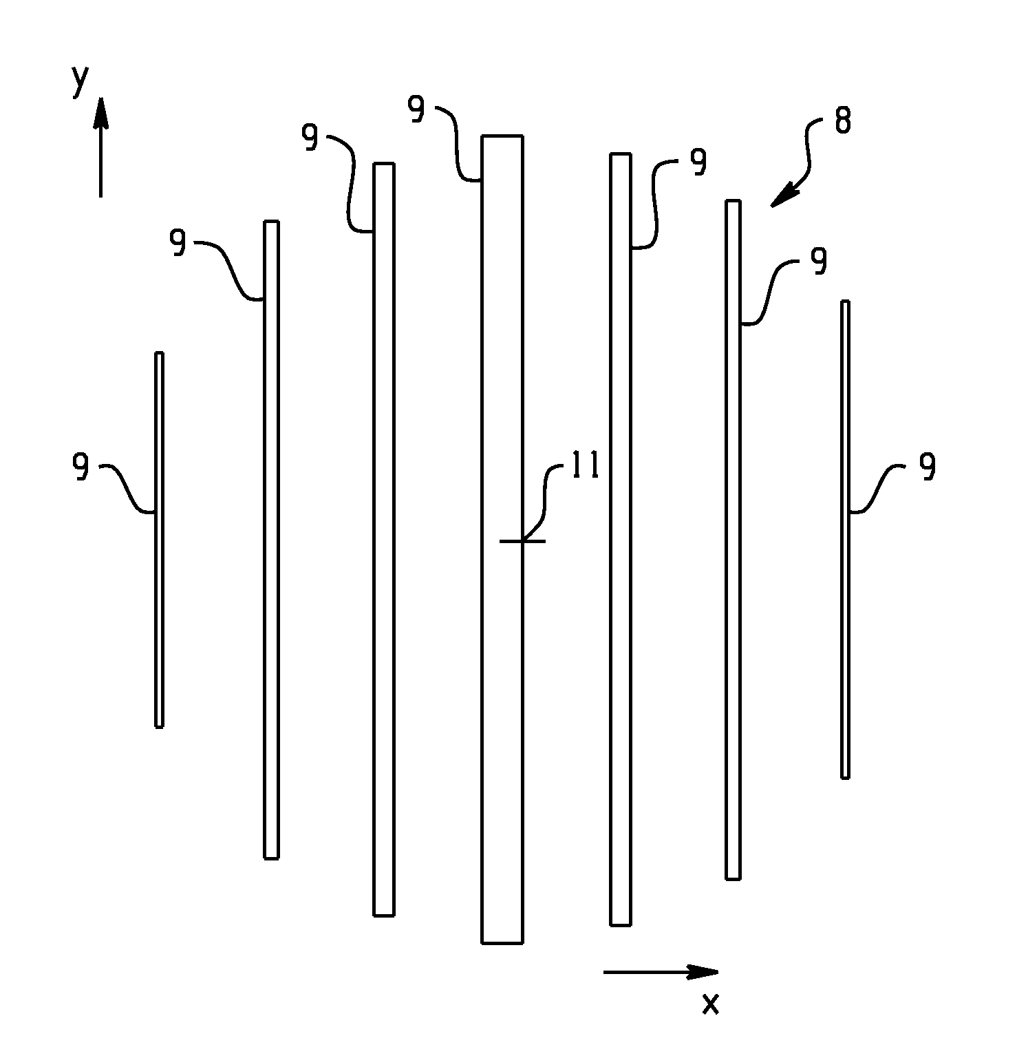
Figure 1 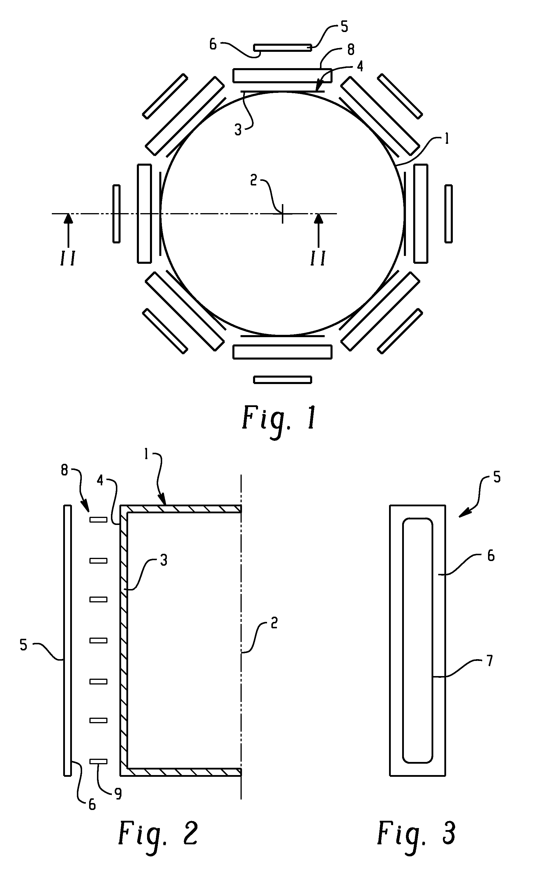
Figure 2 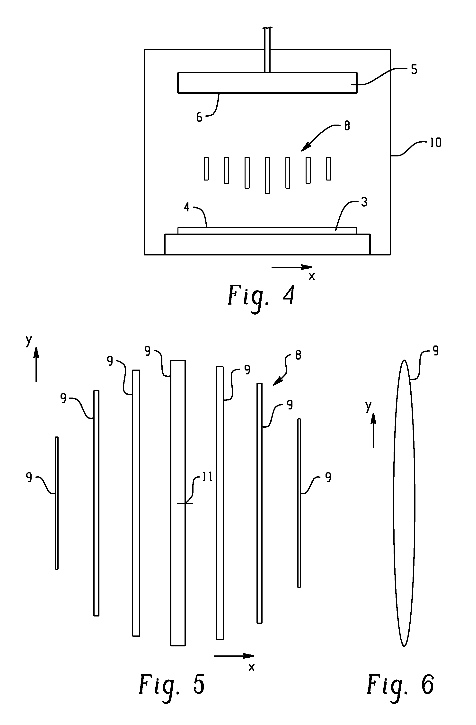
Figure 3
Abstract
Description
FIELD OF THE INVENTION
[0001] The invention relates to a method for producing a directional layer on a substrate surface by means of cathode sputtering, in each case with a nominal directionality in the tangent plane of that surface. Layers of that type are often magnetic layers, or support layers for magnetic layers featuring a preferred direction of magnetization. They are predominantly used in the memory modules of data processing systems, for instance in the read / write heads for hard disks and MRAMs. The invention further relates to a device for implementing the method.PRIOR ART
[0002] A method of that category has been described earlier in U.S. Pat. No. 6,790,482 B2. It provides for a directional magnetic layer to be produced on a flat substrate and permitting easier magnetization in one specific, essentially constant, nominal direction (the so-called easy axis) than in other directions, especially those perpendicular to the nominal direction. For the orientation of the layer, elec...
Examples
Embodiment Construction
[0019]The device shown in FIG. 1-3 is placed in a vacuum chamber (not shown). It features a cylindrical basket 1 that can pivot around an axis 2 and is provided on its outside with holders to which substrates 3 are attached, their flat substrate surfaces 4 facing outward. The substrates 3 may be disks with a diameter of about 200 mm, which, upon completion, will be cut up and used for instance in the fabrication of components for read / write heads. At a certain distance the basket 1 is surrounded by targets 5 in the form of elongated, vertical plates whose target surface 6 is oriented toward the axis 2. The targets 5 are constituted as conventional magnetron targets, meaning that behind the target surface 6 they are provided with magnets that generate in the region of the target surface 6 a magnetic field concentrated around a closed loop 7 (FIG. 3), causing the target 5 to be ablated primarily in that region, with corresponding erosion grooves produced in the target surface 6.
[0020]...