

Combined puncturing wire clip
A puncture wire clip and combined technology, applied in the field of combined puncture wire clips, can solve problems such as complicated operation, and achieve the effects of convenient use, low cost, and simple structure
- Summary
- Abstract
- Description
- Claims
- Application Information
AI Technical Summary
Problems solved by technology
Method used
Image

Examples
Embodiment Construction
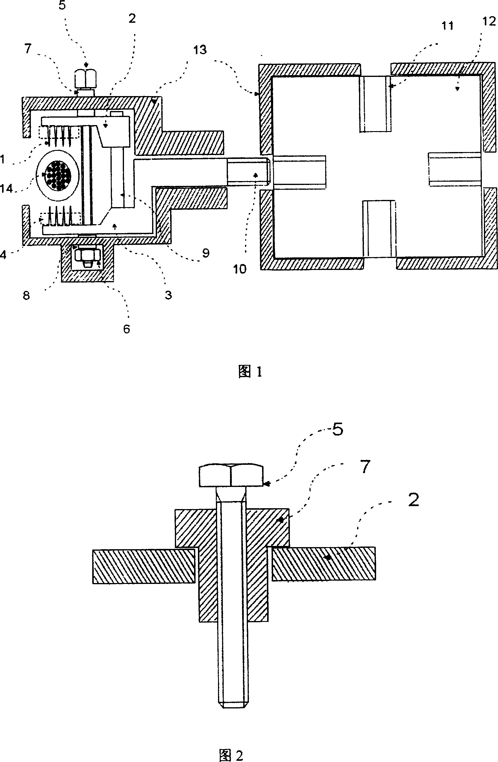
[0009] Specific embodiments of the present invention will be described in detail below in conjunction with technical solutions and accompanying drawings.
[0010] The puncture tool is composed of a steel upper occlusal body 2, a lower occlusal body 3 and a stainless steel thorn block group 1 with an insulating sealing gasket 4 on the thorn block group. A steel column 9 is welded on the lower occlusal body. One end of the upper occlusal body is worn on the upright, and can move up and down through the upright. The torque bolt 5 cooperates with the nut 6 to complete the occlusal operation of the upper and lower occlusal bodies. The engineering plastic insulating pressure pads 7 and 8 insulate the torque bolts. The structure of the insulating pressure pads is shown in FIG. 2 . The conductor is welded and fixed at the tail end of the lower occlusal body, so that an equipotential connection is formed between the conductor and the entire puncture-type cable joint. The thread at th...
PUM
 Abstract
Description
Claims
Application Information