Rotary electromagnetic type uniform tidal current controller

A power flow control and electromagnetic technology, applied in the direction of circuit devices, electrical components, AC network circuits, etc., can solve problems such as harmonic interference, low overload capacity of devices, and reduced reliability of devices

Inactive Publication Date: 2009-03-11
山东严格产业发展有限公司
View PDF5 Cites 0 Cited by
  • Summary
  • Abstract
  • Description
  • Claims
  • Application Information

AI Technical Summary

Problems solved by technology

[0005] The purpose of the present invention is to provide a rotating electromagnetic unified power flow control device to overcome the problem that the main working circuit of the power quality control device in the prior art uses power semiconductor devices, which increases the cost of the device on the one hand and reduces the cost of the device on the other hand. Reliability, and the overload capacity of the device is low, which will generate new harmonic interference defects

Method used


Image

  • Rotary electromagnetic type uniform tidal current controller
  • Rotary electromagnetic type uniform tidal current controller
  • Rotary electromagnetic type uniform tidal current controller

Examples


specific Embodiment approach 1

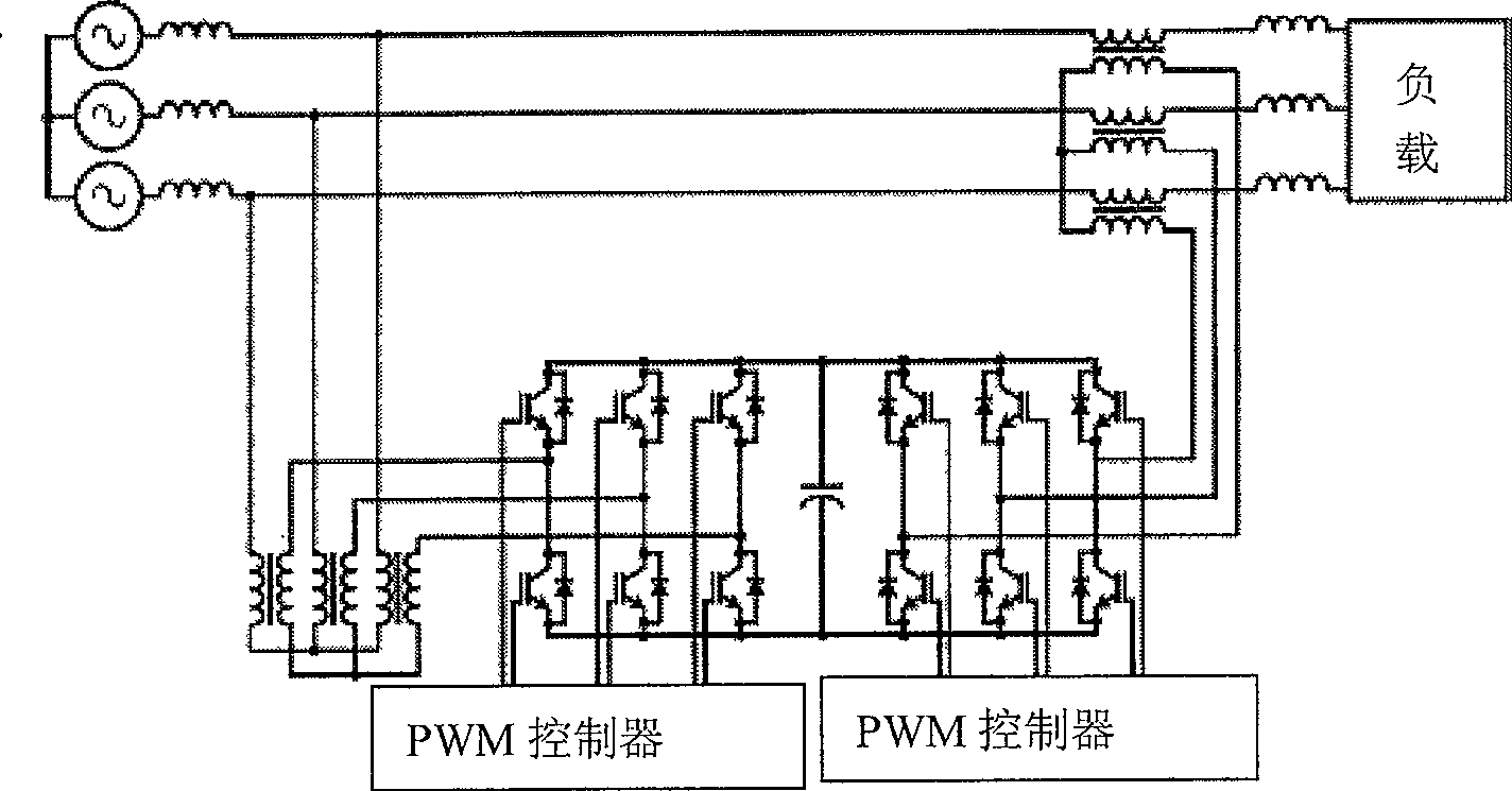
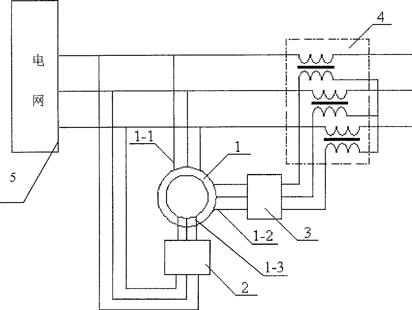
[0008] Specific implementation mode one: the following combination figure 2 This embodiment will be specifically described. This embodiment consists of a wound rotor induction motor 1, an AC excitation power supply 2, an AC chopper 3 and a transformer 4. There are two sets of three-phase symmetrical windings on the stator of the wound rotor induction motor 1, and one set is a parallel winding. 1-1, the other set is the series compensation winding 1-2, one end of the series compensation winding 1-2 is connected to the input side of the AC chopper 3, and the output side of the AC chopper 3 is connected to the primary side of the transformer 4, The rotor windings 1-3 of the wound rotor induction motor 1 are connected to the output end of the AC excitation power supply 2 through slip rings and brushes. The AC excitation power supply is composed of rectification, filtering, inverter and frequency conversion units, which complete the rectification, filtering and inverter of three-...

specific Embodiment approach 2

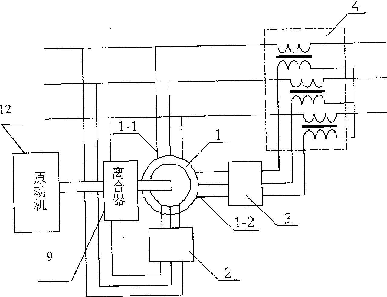
[0012] Specific implementation mode two: the following combination image 3 This embodiment will be specifically described. The difference between this embodiment and the first embodiment is that it also includes a clutch 9 and a prime mover 12, the engine shaft of the prime mover 12 is fixed on the rotor shaft end of the wound rotor induction motor 1 through the clutch 9 to realize coaxial rotation . When the power grid and the load need to continuously compensate active power, the device of the present invention operates in the generator mode, and the prime mover can be used to drive the rotor of the wound rotor induction motor 1, and by controlling the magnitude and frequency of the output current of the AC excitation power supply 2, even When the speed of the prime mover changes, it can also output active power with a constant frequency to the grid and loads to achieve uninterrupted power supply, or to use wind energy, water energy and other energy sources to supplement p...

specific Embodiment approach 3

[0013] Embodiment 3: The difference between this embodiment and Embodiment 2 is that the prime mover can be a power device such as a gas engine, a wind engine, or a water turbine engine. Other composition and connection methods are the same as those in Embodiment 2.


PUM


Abstract

The disclosed apparatus for controlling quality of power supply includes winding type rotor induction motor, AC field power supply, AC chopper, and transformer. Stator of the winding type rotor induction motor includes two sets of symmetry windings in three phases: one set is parallel winding, and the other set is series compensating winding (SCW). One end of SCW is connected to the input end of the AC chopper, and the output end of the AC chopper is connected to primary side of transform. Through slip ring and brush, rotor winding is connected to the output end of the AC field power supply. Comparing with current technique of using power semiconductor device, the invention uses winding type rotor induction motor, providing advantages of reducing cost, raised reliability, simple structure, easy of integration, and preventing harmonic interference.

Description

technical field [0001] The invention relates to a power quality control device, which belongs to the technical field of motors and power electronics. Background technique [0002] With the increasingly widespread application of power electronic devices, the harmonic pollution in the power grid is also becoming more and more serious. In addition, the power factor of many power electronic devices is very low, which also brings additional burden to the grid and affects the quality of power supply. Therefore, eliminating harmonic pollution and improving power factor has become a major issue in power electronics technology. [0003] Typical devices used to compensate reactive power include static var compensators and static var generators. Typical devices used to compensate harmonics are power active filters. A typical device used for power system power flow control is the unified power flow controller. The main structure of the unified power flow controller is as follows: fi...

Claims


Application Information

Patent Timeline
Patent Type & Authority Patents(China)
IPC IPC(8): H02J3/00H02J3/18H02J3/24
CPCY02E40/30
Inventor 寇宝泉张树波李立毅
Owner 山东严格产业发展有限公司
Why Eureka
Try Eureka