Cable identifying method and cable identifying instrument

A cable identification instrument and cable technology, which is applied to the phase angle between voltage and current, instruments, and measuring electricity, can solve the problems of reducing cable identification efficiency, reducing service quality, and cumbersome operations, so as to simplify operation and ensure service Quality, the effect of reducing economic losses

Inactive Publication Date: 2009-05-20
北京宏恩控股有限公司
View PDF9 Cites 2 Cited by
  • Summary
  • Abstract
  • Description
  • Claims
  • Application Information

AI Technical Summary

Problems solved by technology

[0005] From the above-mentioned existing pulse current method, it can be seen that before the cable identification, the target cable must be in a power-off state. On the one hand, it will bring more cumbersome operations and reduce the efficiency of cable identification; It will cause economic loss and reduce the quality of service

Method used


Image

  • Cable identifying method and cable identifying instrument
  • Cable identifying method and cable identifying instrument
  • Cable identifying method and cable identifying instrument

Examples


Embodiment Construction
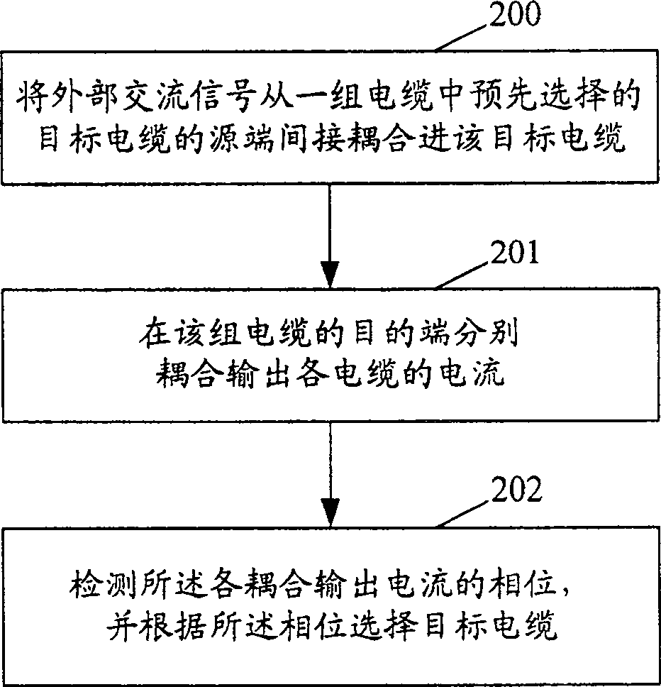
[0044] The core idea of ​​the present invention is: to couple an external AC signal from one end of a pre-selected target cable in a group of cables into the target cable, couple the AC current of each cable to the other end of the group of cables, and detect the AC current of each cable. The phase of the coupled-out current, according to which phase the target cable is selected.

[0045] In order to make the object, technical solution and advantages of the present invention clearer, the present invention will be further described in detail below with reference to the accompanying drawings and preferred embodiments.

[0046] figure 2 It is a flow chart of the cable identification method of the present invention, selecting one end of the target cable from a group of cables in advance, including the following steps:

[0047] Step 200: Indirectly coupling an external AC signal from one end of a target cable in a set of cables into the target cable.

[0048] Step 201: Coupling ...


PUM


Abstract

Through indirect coupling, the method inputs outer AC signals to target cables in a set of cable. The other end of the set of cable outputs coupled AC current of each cable respectively. Detecting phase of each coupled output current, the method selects target cables based on phases. The invention also discloses a cable identification instrument. Before identifying cable, the method does not need to disconnect connections between two ends of each cable and equipment of transformer, switchgear, i.e. cable is in electrification state. Features are: simplifying operation for identifying cables, raised efficiency for identifying cables, reducing emergent loss caused by power cut so as to guarantee quality of service.

Description

technical field [0001] The invention relates to electric system detection technology, in particular to a cable identification method and a cable identification device. Background technique [0002] Identifying the target cable from a group of cables is a very important task in cable engineering. [0003] At present, the widely used cable identification method is the pulse current method, such as figure 1 as shown, figure 1 It is a schematic diagram of the principle of the pulse current method in the prior art, assuming that a group of cables includes two cables L1 and cable L2, the cables L1 and the cables L2 are laid side by side, and the cable L1 is assumed to be the target cable; before identifying the cables, disconnect both ends of the cable L1 The connection with the power transformation and distribution equipment means that the cable is in a de-energized state, and at the same time disconnect the grounding of the metal armor at both ends of the cable L1, such as fi...

Claims


Application Information

Patent Timeline
Patent Type & Authority Patents(China)
IPC IPC(8): G01R25/00G01R31/00
Inventor 高胜友赵秀山
Owner 北京宏恩控股有限公司
Why Eureka
Try Eureka