Shift control device for transmission

A technology for shifting control and transmission housing, which is applied in the field of shifting control equipment to achieve the effects of light and fast shifting operation, preventing frictional resistance and reducing the number of parts

Inactive Publication Date: 2008-10-01
DAIHATSU MOTOR CO LTD
View PDF2 Cites 4 Cited by
  • Summary
  • Abstract
  • Description
  • Claims
  • Application Information

AI Technical Summary

Problems solved by technology

Then, the engagement member elastically biased by the detent engages with the recessed portion, thereby elastically restricting further movement of

Method used


Image

  • Shift control device for transmission
  • Shift control device for transmission
  • Shift control device for transmission

Examples


Example Embodiment

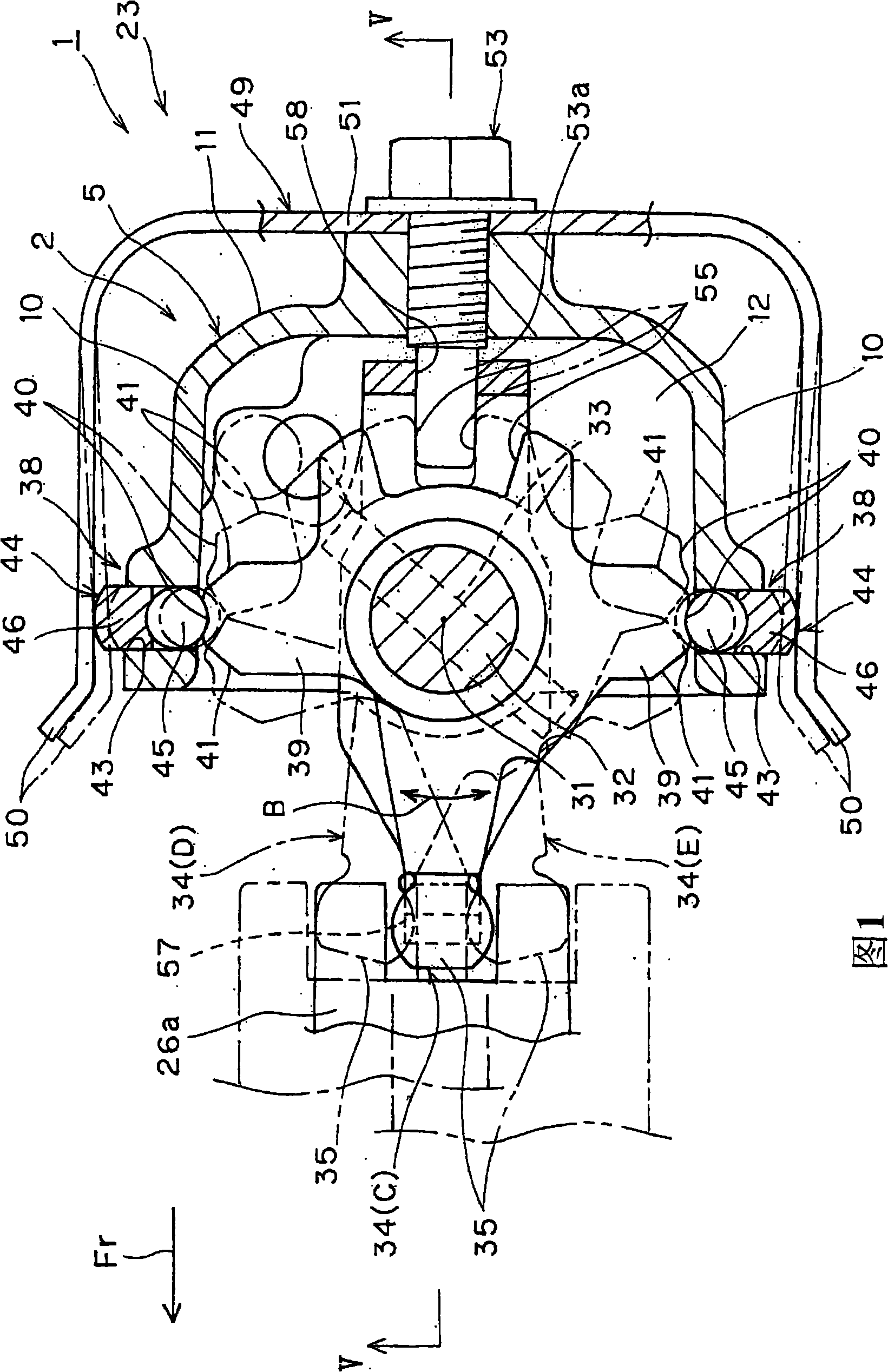
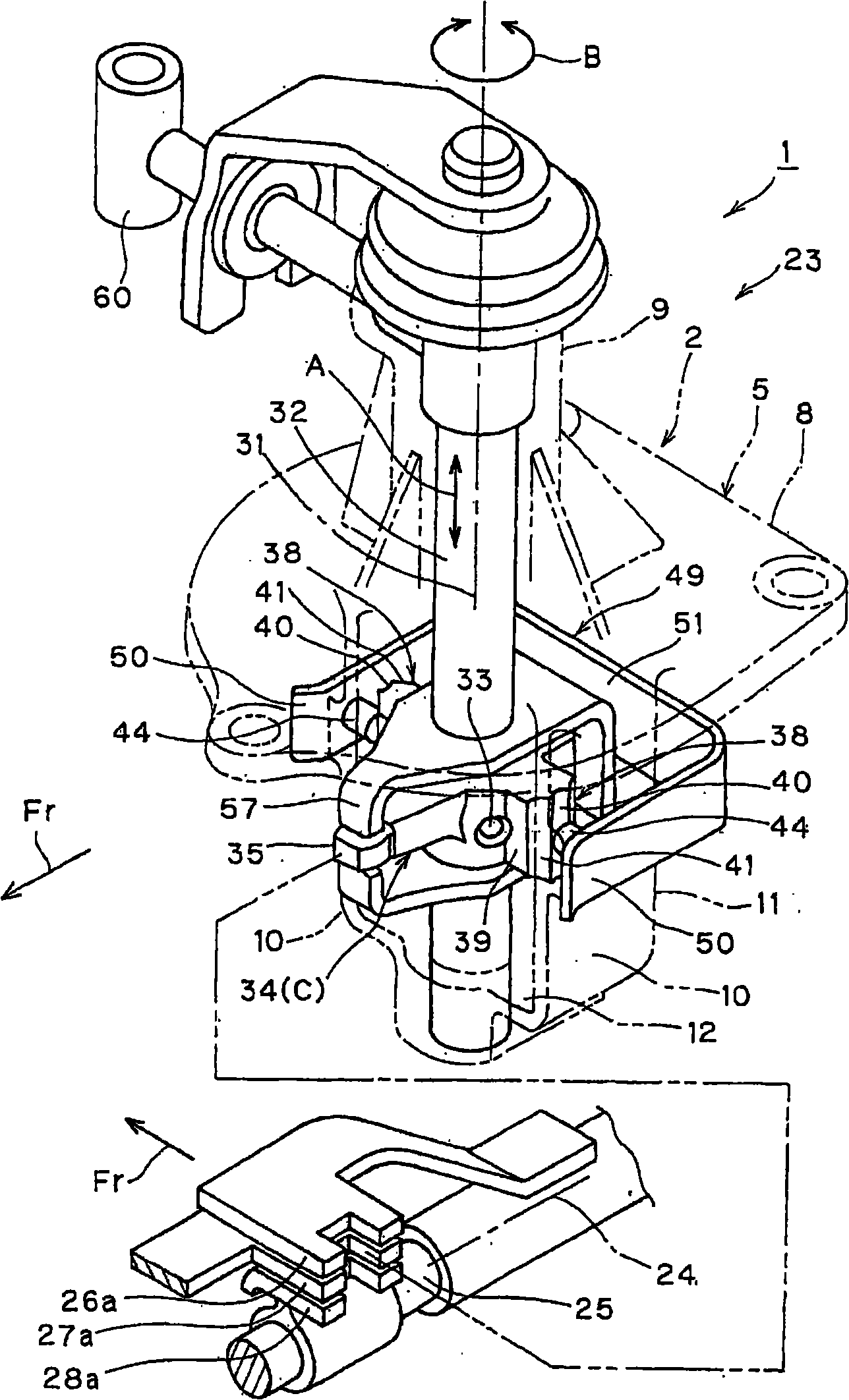
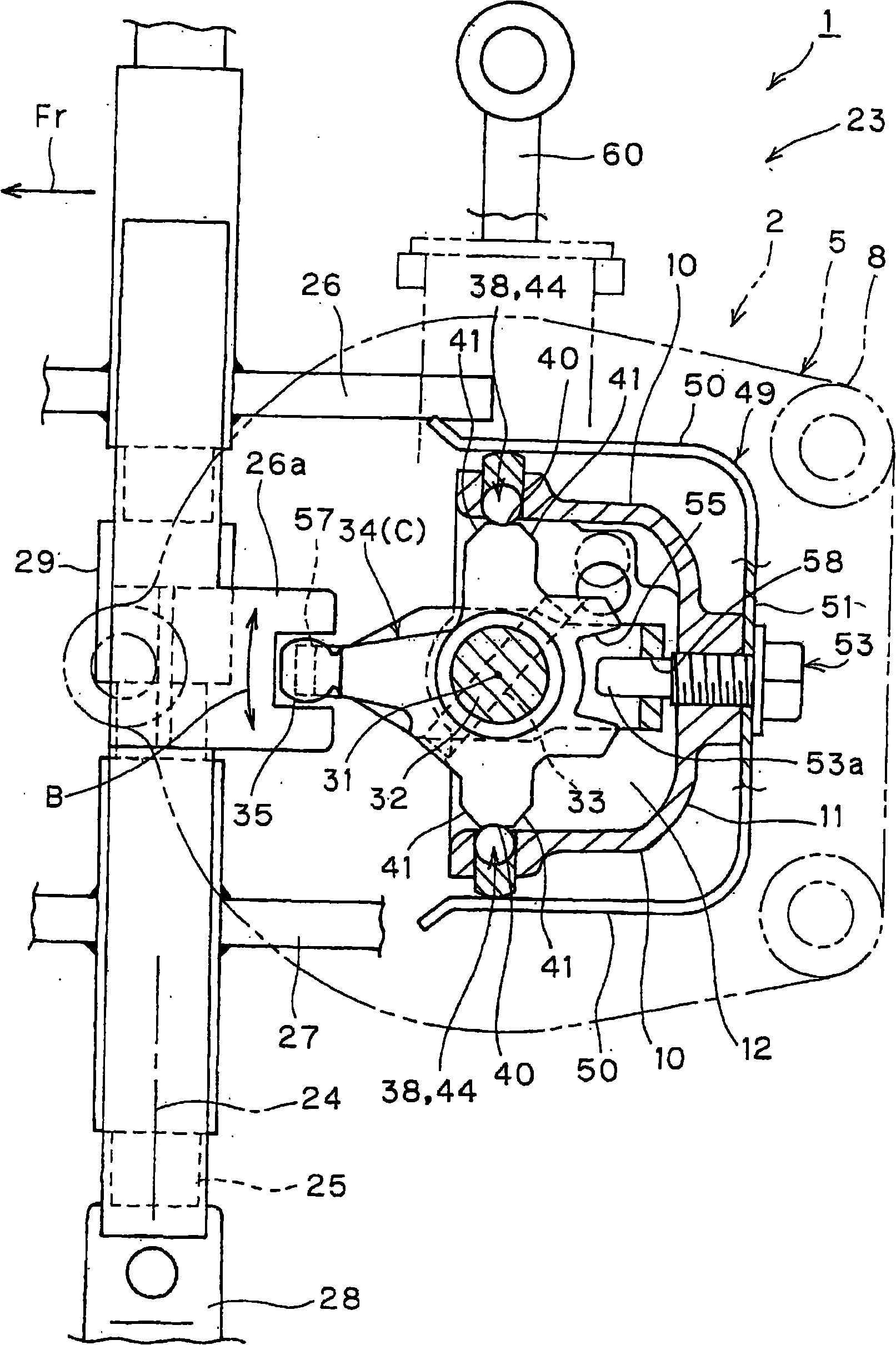
[0033] In order to achieve the purpose of providing a shift control device for a transmission, such a device may have a simplified structure and realize a light and fast shift operation. A typical embodiment of the present invention will be described below.

[0034]That is: the gear shift control device for the transmission includes a fork shaft supported on the transmission housing, a plurality of gear forks arranged to be associated with all gears and supported on the fork shaft, and the head of the gear fork Arranged to be concentrated in one position, the gear selector shaft supported on the transmission housing, the inner rod supported on the gear selector shaft, and the inner rod not only moves in the axial direction of the gear selector shaft, but also It also rotates around the axis of the gear selector shaft to selectively engage with the head of one of the gear forks through movement and rotation caused by the gear shift actuation to establish a link with the selected mo...


PUM


Abstract

A shifting control device (23) comprises an inner pole (34). The inner pole not only moves along the direction of the shift selector shaft (32), but also the pole rotates (B) around the axial line (31) of the to link the shift cross (29) and a head potion (28a) of at least one head section (26a) in the shift crosses (29) via the movement (A) and the rotation (B) to build the linkage with the selected shift cross; a brake device (38), the brake device (38) not only flexibly limits the inner pole (34) to form the rotation (B) of the vacant shift rotating position (C) of the reference position, but also the device flexibly limits the angle, the position reaching the rotating positions (D, E) via the rotation (B) of the vacant shift rotating position (C) in the inner pole (34); the inner pole (34) further rotates at the predetermined rotating positions (D, E) to position the inner pole (34). The invention provides a single cross shaft (25). The brake devices such as the brake device (38) are respectively arranged between the potion of the opposite sides along the shift selector shaft (32) in the inner pole and the gear box shell (2).

Description

[0001] Cross references to related applications [0002] This application claims priority from Japanese Patent Application No. 2007-072577 filed on March 20, 2007, the disclosure of which is hereby incorporated by reference in its entirety. technical field [0003] The present application relates to a shift control device for a transmission. Such a shift control device includes a brake device for positioning an inner lever connected to the shift fork. The inner lever is rotated in a reciprocating manner by the external shift actuation, and the detent locates the inner lever to create a snap feel to the rotational action of the inner lever. Background technique [0004] As for the shift control device of the transmission, a conventional device is disclosed in Patent Document 1 as follows. According to the shift control apparatus for a transmission disclosed herein, the shift control apparatus includes a fork shaft supported in a manner to be slidable in the axial direction ...

Claims


Application Information

Patent Timeline
IPC IPC(8): F16H63/30F16H63/38
CPCF16H63/38
Inventor 中尾章裕嵜迫邦彦北村健
Owner DAIHATSU MOTOR CO LTD
Why Eureka
Try Eureka