Probe device having a light source thereon

A technology of equipment and probes, applied in light sources, electric light sources, point light sources, etc., can solve problems such as incompetence

Inactive Publication Date: 2009-08-26
AGILENT TECH INC
View PDF0 Cites 8 Cited by
  • Summary
  • Abstract
  • Description
  • Claims
  • Application Information

AI Technical Summary

Problems solved by technology

Therefore, this solution is inadequate for its intended purpose

Method used


Image

  • Probe device having a light source thereon
  • Probe device having a light source thereon
  • Probe device having a light source thereon

Examples


Embodiment Construction

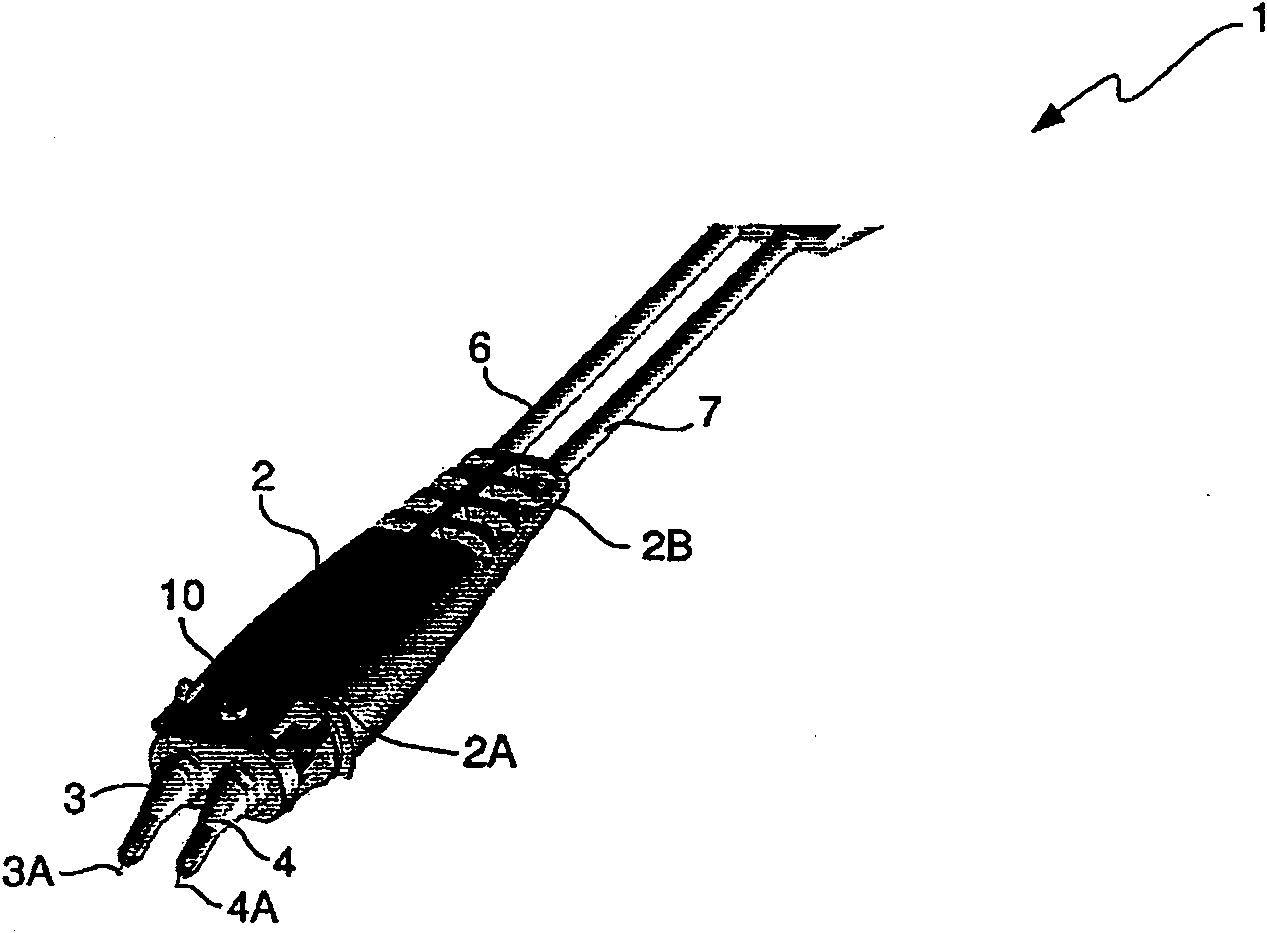
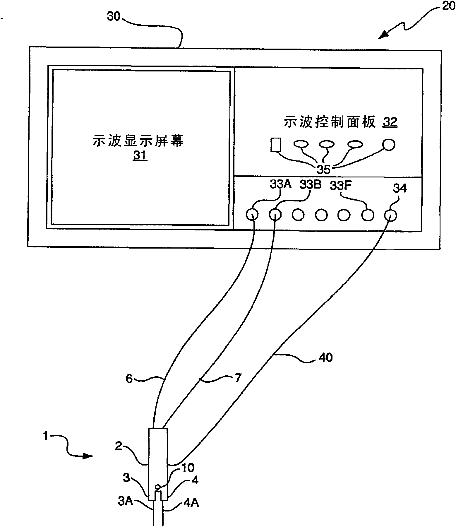
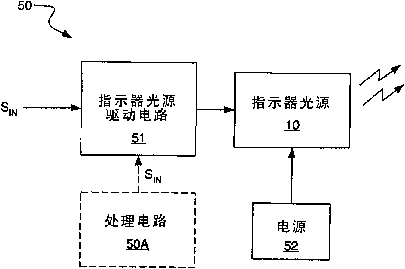
[0019] According to the present invention, there is provided a probe device having a light source thereon. According to one embodiment, the light source operates as a visual indicator to provide a visual indication of whether there is a good connection between the tip of the probe device and the desired contact point on the DUT. According to another embodiment, the light source operates as an illumination source to illuminate the probe tip and the contact pads on the DUT when a user is attempting to place the probe tip into contact with the contact pads on the DUT. According to another embodiment, the light source performs the dual function of providing a visual indication of connection status as well as illuminating the probe device tip and the desired contact point on the DUT.

[0020] Various probe device configurations are possible that enable the objects of the present invention to be achieved. Some examples of possible configurations will now be described with reference...


PUM


Abstract

A probe device is provided that has light source thereon that can be activated and deactivated. In accordance with an embodiment, the light source operates as a visual indicator to provide a visual indication of whether a good connection exists between the tips of the probe device and the intended contact points on the DUT. In accordance with another embodiment, the light source operates as a source of illumination to illuminate the probe tips and the contact pads on the DUT as the user is attempting to place the probe tips in contact with the contact pads on the DUT. In accordance with yet another embodiment, the light source performs the dual functions of providing a visual indication of connection status and of illuminating the probe device tips and the intended contact points on the DUT.

Description

technical field [0001] The present invention relates to electrical probe apparatus for measuring electrical signals on conductors of a device under test (DUT). More specifically, the present invention relates to a probe device having a light source disposed thereon. Background technique [0002] A probe device is a device that has two arms, sometimes referred to as a "substrate" or "blade," that are mechanically coupled to each other at the distal ends of the arms and have a fixed A conductive tip on the proximal end of the arm. During testing of the DUT, these tips are placed in contact with various conductors of the DUT for sensing electrical signals propagating through the conductors of the DUT. Probe devices are typically adjustable to bring the probe tips closer together and farther apart so that the span width between the tips is adjustable to accommodate varying DUT physical layouts. The electrical signal read out by the tip is passed from the tip to other circuits...

Claims


Application Information

Patent Timeline
Patent Type & Authority Applications(China)
IPC IPC(8): G01R1/067G01R31/00F21V23/00H05B37/02F21W131/403F21Y101/02
CPCG01R1/06788
Inventor 詹森·A·斯万姆詹姆斯·E·坎农肯尼·约翰逊
Owner AGILENT TECH INC
Why Eureka
Try Eureka