Triggering method for serial peripheral interface bus signal

A serial peripheral interface and bus signal technology, applied in the direction of digital variable display, etc., can solve the problems of unfavorable measured signal capture and positioning and subsequent analysis, and achieve the effect of improving efficiency and analysis

Inactive Publication Date: 2010-09-08
SOUTHEAST UNIV
View PDF0 Cites 0 Cited by
  • Summary
  • Abstract
  • Description
  • Claims
  • Application Information

AI Technical Summary

Problems solved by technology

Traditional measuring instruments can only trigger and collect SPI serial bus signals through simple trigger methods such as edges, which is not conducive to the capture, positioning and subsequent analysis of the measured signal

Method used


Image

  • Triggering method for serial peripheral interface bus signal
  • Triggering method for serial peripheral interface bus signal
  • Triggering method for serial peripheral interface bus signal

Examples


Embodiment 1

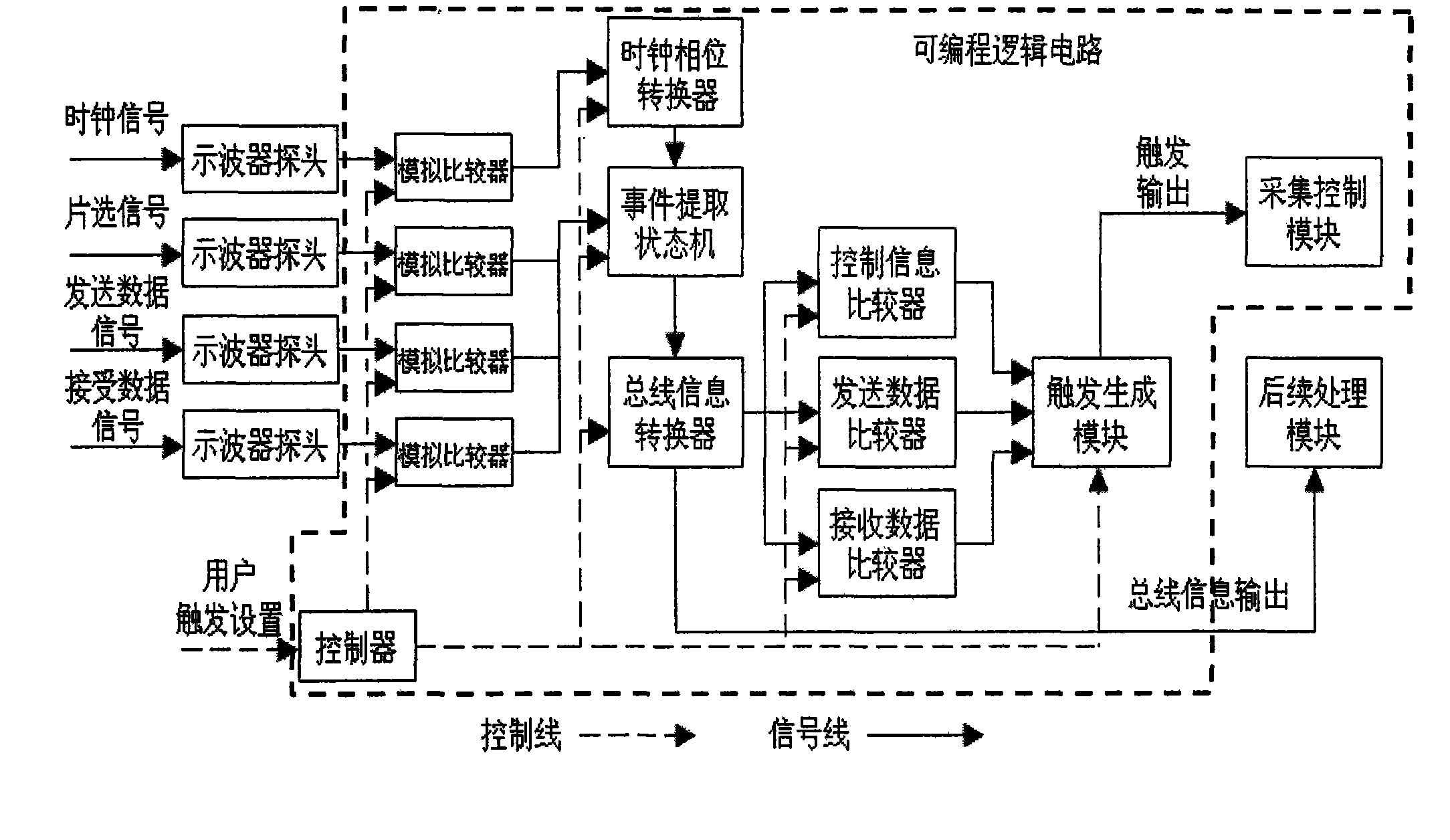
[0067] The invention provides a method for analyzing and triggering an SPI serial bus signal: adjusting the clock phase on the input serial bus according to the SPI serial bus clock operating parameters set by the user, utilizing a synchronous state machine to Extract and convert the information transmitted on the SPI serial bus, compare the converted bus information with the trigger conditions set by the user and the combined relationship between the conditions, when the two match, output the trigger signal, and at the same time transmit the information transmitted on the SPI serial bus For other modules of the measuring instrument, further signal analysis is done. The whole method provides efficient SPI serial bus signal analysis and trigger functions. Fig. 1 is a block diagram of modules of the present invention, and its principle is specified below:

[0068] The SPI serial bus signal is input into the measuring instrument through the probe, and the input analog signal is ...


PUM


Abstract

The invention discloses a triggering method for a serial peripheral interface bus signal, which can accurately and rapidly provide the analysis and triggering functions of the serial peripheral interface bus signal for measuring equipment. The method comprises the following steps: discriminating the level fluctuation of a serial peripheral interface bus by using a synchronous state machine; converting discrimination results into information sent by the bus; inputting the information into a comparator to be triggered and compared; outputting a trigger signal to outside when the information accords with trigger conditions; and independently outputting the information sent by the bus to a subsequent module of the measuring equipment to complete further signal analysis. The analysis and triggering method for the serial peripheral interface bus signal provided by the invention is favorable for improving the capability of acquiring and analyzing the serial peripheral interface bus signal bythe measuring equipment.

Description

technical field [0001] The invention relates to a triggering method of a serial peripheral interface bus signal in a measuring instrument, in particular to a triggering method of a serial peripheral interface bus (hereinafter referred to as SPI serial bus) signal in a digital oscilloscope. Background technique [0002] At present, with the increasingly widespread application of the SPI serial bus, its debugging process becomes more and more complicated, because in the SPI serial bus, all signals (including clock signals, chip select signals, sending and receiving data signals) are in the form of The serial mode is transmitted on the wire, and this serial mode of transmission puts forward higher requirements for the analysis and trigger functions of the measuring instrument. Traditional measuring instruments can only trigger and collect SPI serial bus signals through simple trigger methods such as edges, which is not conducive to the capture, positioning and subsequent analys...

Claims


Application Information

Patent Timeline
Patent Type & Authority Patents(China)
IPC IPC(8): G01R13/02
Inventor 高礼忠张岩任钊孔凡洪
Owner SOUTHEAST UNIV
Why Eureka
Try Eureka