

Show box
A technology for display cabinets and showrooms, applied in the field of display cabinets, which can solve the problems of cumbersome adjustment operations, difficulty in controlling the direction of irradiation, and large size of the main body of the lighting device, so as to achieve the effect of uniform light quantity
- Summary
- Abstract
- Description
- Claims
- Application Information
AI Technical Summary
Problems solved by technology
Method used
Image

Examples
Embodiment 1
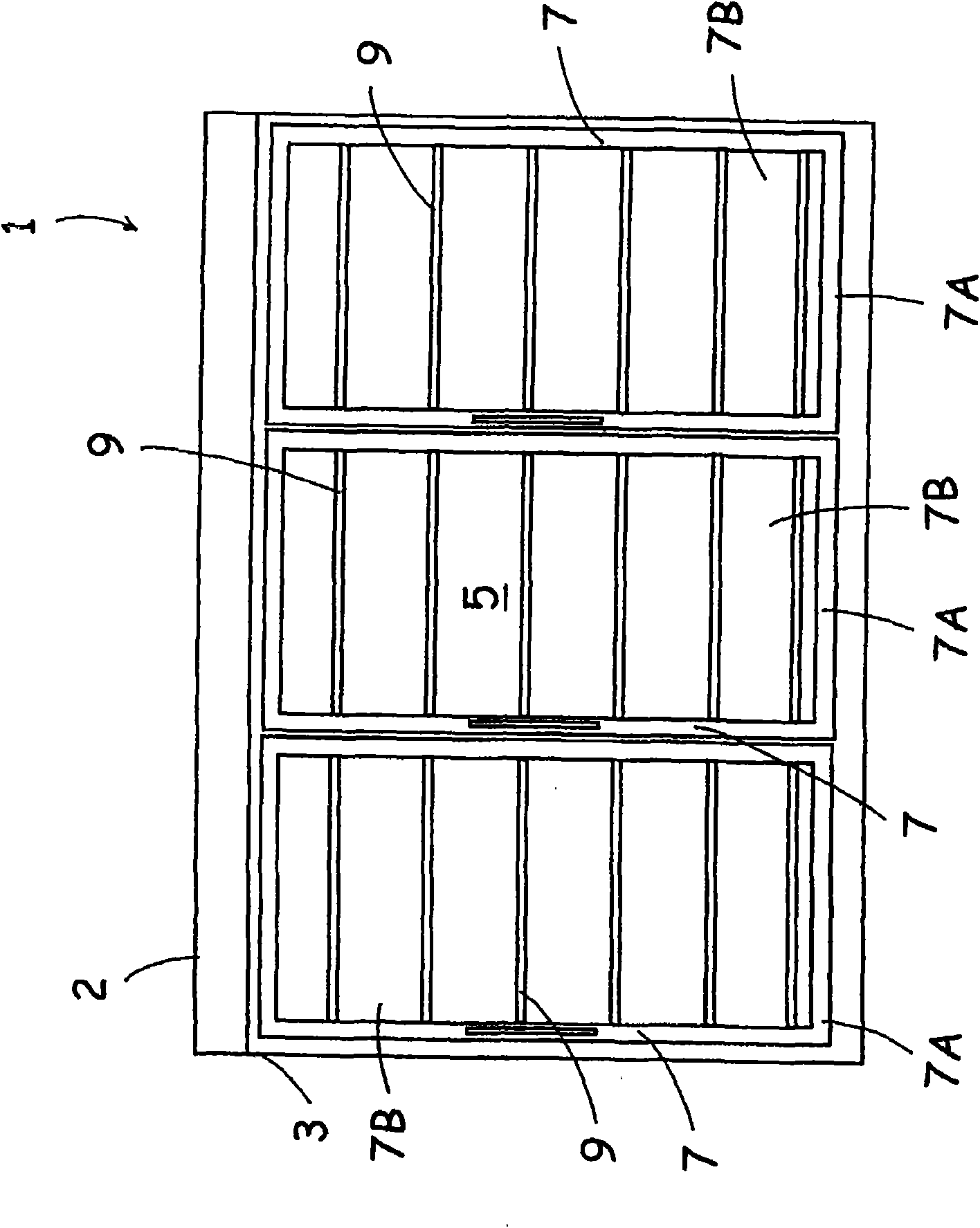
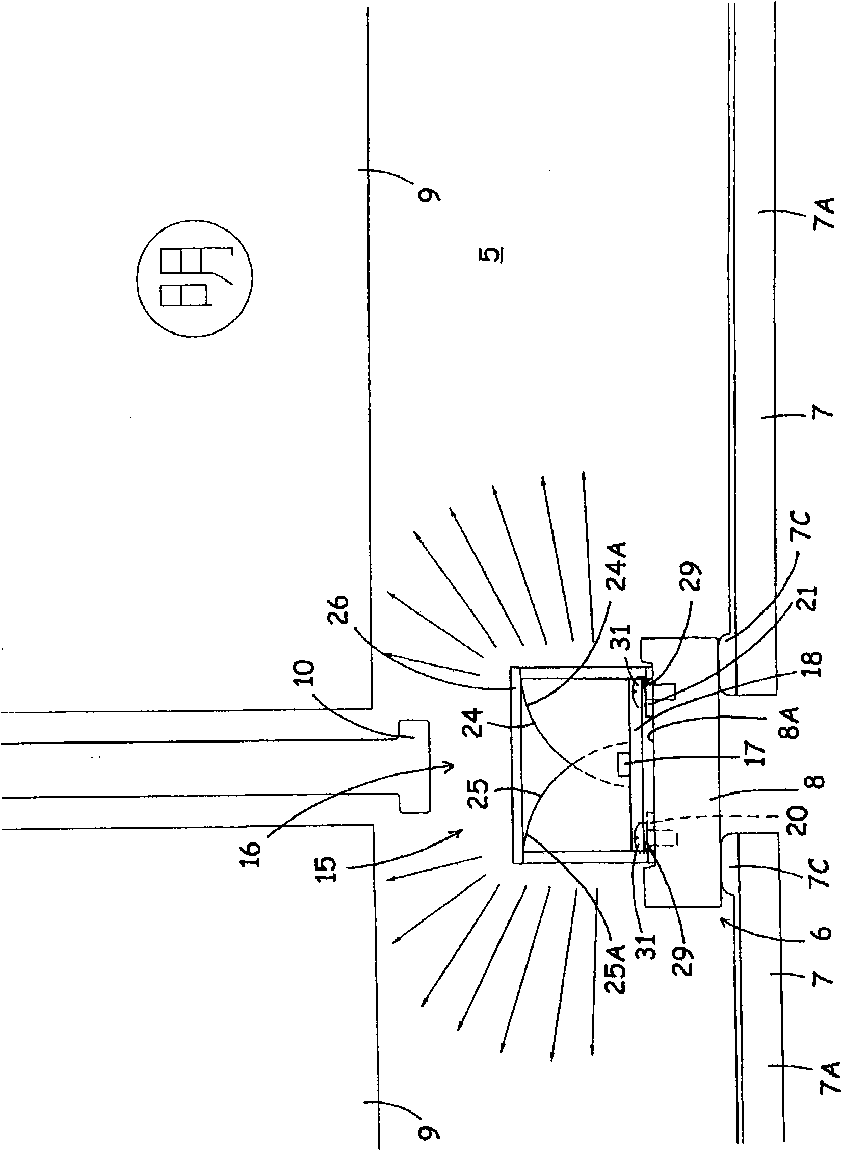
[0070] First, refer to figure 1 and figure 2 The showcase 1 as Example 1 is demonstrated. figure 1 Represents the front view of the showcase 1 to which the present invention is applied, figure 2 A partially enlarged cross-sectional view of the showcase 1 is shown. The showcase 1 is composed mainly of a heat-insulating box (insulation wall) 2 opened in the front of a low-temperature showcase installed in a supermarket, a convenience store, or the like.
[0071] The heat-insulating box 2 is composed of an outer box 3 made of a steel plate opened at the front; and an inner box (not shown) made of a steel plate or a hard resin, which is inserted at intervals and opened at the front, in the outer box 3. ; and a heat insulating material formed by foaming and filling polyurethane foam (polyurethane) between the outer case 3 and the inner case.
[0072] Constitute showroom 5 in this inner box, and switch from the upper end of the front opening 6 of showroom 5 to the lower end wi...
Embodiment 2
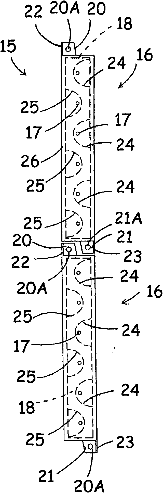
[0120] Below, refer to Figure 11 and Figure 12 The lighting device 40 which is Example 2 provided in the said showcase 1 is demonstrated. Figure 11 It is a partial enlarged sectional view of the showcase 1 using the lighting device 40, Figure 12 is a perspective plan view of a portion of the lighting device 40 . This illuminating device 40 is constituted by a plurality of LED illuminating members 41 having substantially the same configuration as the LED illuminating members 16 of the illuminating device 15 of the first embodiment. It is also constituted by arranging a plurality of related LED lighting components 41 side by side up and down on the rear surface 8A of the pillar 8. The LED lighting components 41 are composed of the following: a substrate 18 on which a plurality of LED elements 17 are arranged; A plurality of reflective members 24 . . . , 25 . . . of light irradiated by the element 17; In this embodiment, since the structure other than the cover member 42 ...
Embodiment 3
[0130] Below, refer to Figure 13 The lighting device 45 as the third embodiment installed in the showcase 1 will be described. Figure 13 is a perspective plan view of a part of the lighting device 45 . The lighting device 45 in this embodiment is the same as the above-mentioned embodiment 1, and it is all formed by arranging a plurality of LED lighting components 46 side by side on the rear surface 8A of the pillar 8. The LED lighting components 46 are composed of the following: a plurality of The substrate 48 of the LED elements 17 ; the plurality of reflection members 24 . . . , 25 .
[0131] On a single substrate 48 constituting the LED lighting unit 46, as in the first embodiment, a plurality of LED elements 17 are arranged on a substantially straight line in the vertical direction or alternately shifted to one side and the other side in the horizontal direction, The first reflective member 24 and the second reflective member 25 are respectively arranged corresponding ...
PUM
 Abstract
Description
Claims
Application Information