Seamless LCD joint method and special image transmission device

A transmission device, seamless splicing technology, applied in the direction of identification device, optics, instrument, etc., can solve the problem of incomplete and discontinuous images, achieve easy popularization and application, simple and easy technical means, and ensure continuity and integrity. Effect

Inactive Publication Date: 2009-12-02
GUANGDONG VTRON TECH CO LTD
View PDF0 Cites 60 Cited by
  • Summary
  • Abstract
  • Description
  • Claims
  • Application Information

AI Technical Summary

Problems solved by technology

[0003] The purpose of the present invention is to overcome the shortcomings and deficiencies of the above-mentioned prior art, and provide a method for LCD seamless splicing. The present invention solves the technical problem of incomplete and discontinuous images displayed at the splicing places of LCD splicing screens in the prior art.

Method used


Image

  • Seamless LCD joint method and special image transmission device
  • Seamless LCD joint method and special image transmission device
  • Seamless LCD joint method and special image transmission device

Examples


Embodiment 1

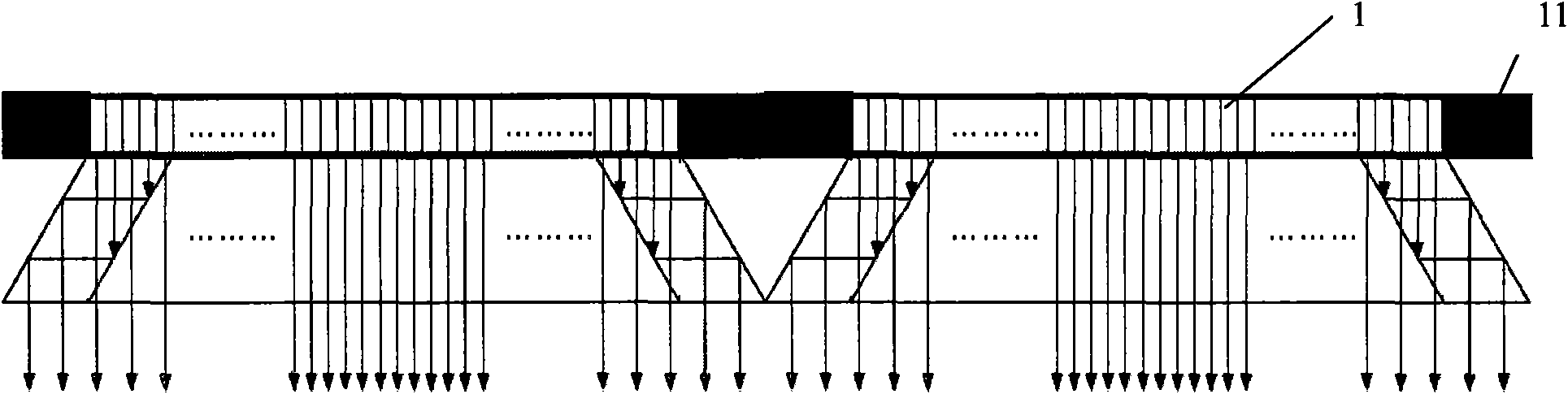
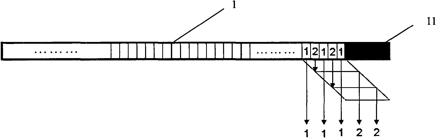
[0031] Such as Figure 1~4 As shown, the LCD seamless splicing method in this embodiment is to select an area equal to the width of the frame as the image transmission area inside the frame of each LCD display unit (that is, in the image display area), and use columnar display in this area. The method displays two images at the same time, the two images are the image to be displayed in the area itself and the image to be displayed at the frame; the image to be displayed at the frame is separated by an image transmission device and transmitted to the frame to cover the frame , forming a frameless display unit, thereby realizing seamless LCD splicing display.

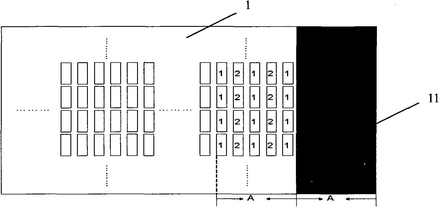
[0032] Such as figure 2 As shown, image 1 represents the image to be displayed in the image transmission area, and image 2 represents the image to be displayed at the frame 11 of the LCD. The function of the image transmission device is to separate the image 2 and guide it to the frame 11, while maintaining the normal ...

Embodiment 2

[0035] In this embodiment, except the following features, other features are the same as in Embodiment 1:

[0036] Such as Figure 5 As shown, the image transmission device is two sets of matched micro-prism arrays, one of which is located above the image transmission area, and the other is located at the border, and the size of each micro-prism is the same as that of the image displayed in the image transmission area. The pixel sizes are the same; the microprism array close to the display surface of the LCD display unit 1 guides the light beam corresponding to the image 2 to the direction of the frame 11, and the microprism array at the frame 11 guides the light beam corresponding to the image 2 to the display direction of the image.

Embodiment 3

[0038] In this embodiment, except the following features, other features are the same as in Embodiment 1:

[0039] Such as Figure 6As shown, the image transmission device includes a rhomboid prism and a polarization conversion device. One end of the rhomboid prism is located above the image transmission area, and the other end is located above the frame. The polarization conversion device is arranged between the rhomboid prism and the between image transfer areas.

[0040] The polarization conversion device includes two transparent substrates, a transparent material and an optically active substance arranged between the two transparent substrates, the distribution of the optically active substance and the transparent material corresponds to the display state of the two images, and the transparent material is A transparent resin material, the optically active substance is a liquid crystal material. The two transparent substrates are composed of glass substrates, alignment fi...


PUM


Abstract

The invention discloses a seamless LCD joint method, which comprises the following steps that: an area larger or equal to an LCD frame in length and width is selected in an image display area of an LCD display unit to serve as an image transmission area; two images which are an image required to be displayed in the area and an image required to be displayed at the position of the frame respectively are displayed in the image transmission area by using a row / column division or time / frame division display method; the image required to be displayed at the position of the frame is separated and transmitted by an image transmission device to the position of the frame and to cover the frame part to form a frameless display unit, so that an image on an LCD display unit can be well jointed with an image on an adjacent LCD display unit to realize seamless display to realize the continuity and integrity of a seamless of a whole image on a large-screen LCD joint display screen. The device is simple and easily implementable in technical means and convenient in market promotion and application.

Description

technical field [0001] The invention relates to large-screen display technology, in particular to an LCD seamless splicing method and a special image transmission device. Background technique [0002] The existing large-screen LCD display screen is formed by splicing several LCD display units. Due to the requirements of the drive circuit and production process around the panel of the LCD display unit, a frame with a certain space needs to be reserved around the image display area of ​​each LCD display unit (the frame is a non-image display area), and the image cannot be displayed on the frame. Generally, the width of the non-image display area of ​​the frame exceeds 10 mm, and becomes wider as the size of the panel increases. Therefore, when splicing the display screen, it is easy to form a larger splicing seam between adjacent LCD display units, and the splicing seam is the sum of the frame widths of two adjacent LCD display units (generally, the width exceeds 20mm. ), ca...

Claims


Application Information

Patent Timeline
Patent Type & Authority Applications(China)
IPC IPC(8): G09F9/35G02F1/133
CPCG02F2001/13355G02F1/13336G02F1/13471G02F2001/133562G02F1/133555G02F1/31G02F1/13355G02F1/133562
Inventor 孟凡华黄永峰
Owner GUANGDONG VTRON TECH CO LTD
Why Eureka
Try Eureka