Pneumatic pollen transmission device

A pneumatic pollen technology, applied in the field of gardening tools, can solve the problems of pollination success rate, low accuracy, and low work efficiency, and achieve the effect of convenient operation, small size and high pollination success rate

Inactive Publication Date: 2010-03-03
CHENGDU JUNFENG TECH DEV
View PDF0 Cites 4 Cited by
  • Summary
  • Abstract
  • Description
  • Claims
  • Application Information

AI Technical Summary

Problems solved by technology

[0002] When horticulturists pollinate flowers and fruits, they usually use brushes and other tools to pollinate. This kind of operation is not only affected b

Method used


Image

  • Pneumatic pollen transmission device

Examples


Example Embodiment

[0011] The present invention will be further described below with reference to the drawings and embodiments.

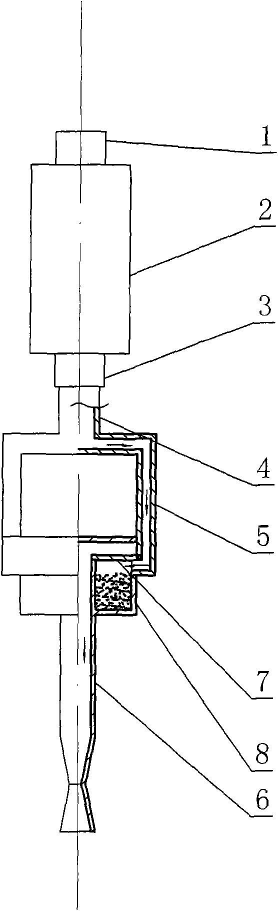
[0012] The pneumatic pollen spreader is composed of a one-way air inlet valve 1, an air bag 2, a one-way air outlet valve 3, a main pipe 4, a side pipe 5, a nozzle 6, a cover sheet 7 and a pollen bucket 8. Among them, the top and bottom of the airbag 2 are respectively connected with a one-way air inlet valve 1 and a one-way air outlet valve 3, the lower end of the one-way air outlet valve 3 is connected with the main pipe 4, and the lower end of the main pipe 4 is opposite to the two inverted L shapes The side pipes of 5 are connected. The lower ends of the two side pipes 5 are respectively connected to and communicated with the two sides of a cylindrical pollen bucket 8 with a closed top. The inner part of the pollen bucket 8 is provided with an elastic cover 7 to seal the lower half of the pollen bucket 8. The nozzle 6 is a straight pipe with a taper at the lower end...


PUM


Abstract

The invention relates to a garden tool, in particular to a pneumatic pollen transmission device which comprises a one-way air inlet valve, an air chamber, a one-way air outlet valve, a main pipe, sidepipes, a spray pipe, a cover plate and a pollen hopper, wherein the bottom of the air chamber is connected with the one-way air outlet valve, the lower end of which is connected with the main pipe, and the lower end of the main pipe is communicated with the two reverse L-shaped side pipes with the opposite directions; the lower ends of the two side pipes are respectively connected and communicated with two sides of the cylindrical pollen hopper with a closing top end; and the pollen hopper is internally provided with the elastic cover plate used for sealing the lower half part of the pollen hopper. The pneumatic pollen transmission device has higher alignment performance and pollination success rate, and can be operated by a single hand.

Description

technical field [0001] The invention relates to a garden tool, in particular to a pneumatic pollen spreader. Background technique [0002] Horticulturalists usually use brushes and other tools to pollinate flowers and fruits. Such operations are not only affected by low pollination success rate and accuracy, but also low work efficiency, which can no longer meet the needs of current economic development. Contents of the invention [0003] In order to solve the deficiencies of the prior art, the invention provides a pneumatic pollen spreader with higher working efficiency and pollination success rate. [0004] The solution to the technical problem of the present invention is: the pneumatic pollen spreader is composed of a one-way air inlet valve, an air bag, a one-way air outlet valve, a main pipe, a side pipe, a spray pipe, a cover sheet and a pollen hopper. Wherein, the top and the bottom of the airbag are respectively connected with a one-way air inlet valve and a one-w...

Claims


Application Information

Patent Timeline
IPC IPC(8): A01H1/02
Inventor 许小玲
Owner CHENGDU JUNFENG TECH DEV
Why Eureka
Try Eureka