Unlock instant, AI-driven research and patent intelligence for your innovation.

Imaging device, imaging method, and imaging program

A camera device and image technology, applied in the directions of image communication, TV, color TV components, etc., can solve the problems of inability to recognize, white objects, inability to distinguish objects and noise, etc., to achieve the effect of improving accuracy

Inactive Publication Date: 2013-06-26
FUJITSU LTD
View PDF9 Cites 0 Cited by
  • Summary
  • Abstract
  • Description
  • Claims
  • Application Information

AI Technical Summary

Problems solved by technology

like Figure 22 As shown, in the case of shooting in low brightness and dark places, it is impossible to distinguish between objects and noise, and the recognition rate is low.
On the contrary, when the brightness is too high, the object cannot be recognized due to the saturation of the brightness, and the recognition rate is still low.

Method used


Image

  • Imaging device, imaging method, and imaging program
  • Imaging device, imaging method, and imaging program
  • Imaging device, imaging method, and imaging program

Examples


Embodiment 1

[0058] First, the outline and features of the imaging device of the first embodiment will be described. The imaging device of the first embodiment performs adjustment of exposure (adjustment of camera parameters) based on the illuminance distribution of the entire monitoring range. That is, considering the difference in illuminance for each position on the real space (the space where the object to be monitored exists), the exposure is adjusted for each position where the object is detected so that the entire monitoring range becomes recognizable brightness.

[0059] figure 1 It is a figure which shows an example of the illuminance distribution of a monitoring range. As shown in the figure, the illuminance distribution of the monitoring area is determined by the sum of the amount of ambient light irradiated onto the monitoring area from a light source such as the sky and the amount of illumination light for illuminating the monitoring area. However, ambient light and illumina...

Embodiment 2

[0117] Heretofore, the embodiments of the present invention have been described, but the present invention can also be implemented in various forms other than the above-mentioned embodiment 1. Therefore, another example included in the present invention will be described below as Example 2. FIG.

[0118] (1) When it is difficult to take pictures with brightness suitable for recognition in the entire monitoring area

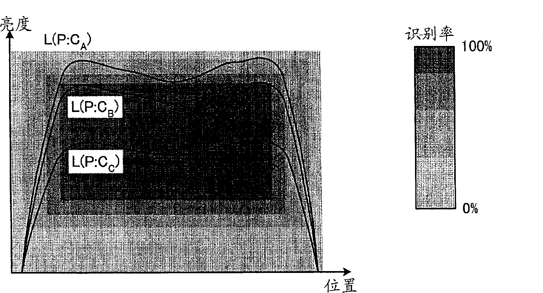
[0119] In the above-mentioned first embodiment, the camera parameters are determined so that the brightness of the object at a certain reference position is the most suitable value for recognition. However, sometimes the monitoring range is wide and it is difficult to carry out the monitoring with the brightness suitable for recognition in the entire monitoring range. photography.

[0120] In this case, it is expected that the recognition rate will decrease in an area that cannot be photographed with a brightness suitable for recognition. However, generally, the ...


PUM


Abstract

In an image capturing apparatus (100), an image recognition device (130) detects an object to be monitored and calculates an object luminance and object coordinates by performing a recognition process on the detected object. A control device (140) calculates a position and an illuminance in space where the object exists on the basis of the object luminance and the objet coordinates, calculates a camera parameter on the basis of the calculated position and illuminance and a present camera parameter, and controls the camera parameter of a video image capturing device (120) according to the calculated camera parameter, so that the exposure amount is adjusted.

Description

technical field [0001] The present invention relates to an imaging device and an imaging method for detecting and photographing an object. Background technique [0002] In conventional image surveillance, an object to be monitored is detected, recognition of the detected object is performed, and characters written on the object are read (for example, refer to Patent Document 1, Patent Document 2, etc.). In this image monitoring, in order to obtain a high recognition rate (ratio of successfully recognized objects), it is necessary to photograph the object itself to be recognized with a brightness suitable for recognition. [0003] In particular, in outdoor image monitoring, etc., the illuminance environment changes constantly due to the weather, sunlight conditions, etc. In order to obtain a high recognition rate even in such an illuminance environment, it is necessary to adjust the amount of light incident on the imaging device (exposure amount) , so that objects are always...

Claims


Application Information

Patent Timeline
IPC IPC(8): H04N5/225
CPCH04N5/2352H04N5/2351H04N5/23219H04N23/611H04N23/72H04N23/71H04N23/75
Inventor 末延望瀬川英吾
Owner FUJITSU LTD