22.5-degree square rotary switch

A rotary switch, square technology, applied in the direction of electric switches, electrical components, circuits, etc., can solve the problems of large rotation angle of the knob, can not meet the needs of multiple gears, can not meet the requirements of high power, etc., to achieve clear gears , the strength is light, and the effect of prolonging life

Inactive Publication Date: 2011-01-12
NINGBO JIALIN ELECTRONICS
View PDF4 Cites 5 Cited by
  • Summary
  • Abstract
  • Description
  • Claims
  • Application Information

AI Technical Summary

Problems solved by technology

[0002] The existing rotary switches basically use the reeds to directly contact the electricity, without silver contacts, and it is difficult to ensure a good contact state between the reeds, which cannot meet the requirements of high power. In particular, the rotation angle of the knob is too large. Can not meet the needs of multi-gear, from the actual use requirements of those multi-gear, high-power small heaters, it has been unable to meet, so it is necessary to improve the rotary switch of the prior art

Method used


Image

  • 22.5-degree square rotary switch
  • 22.5-degree square rotary switch
  • 22.5-degree square rotary switch

Examples


Embodiment 1

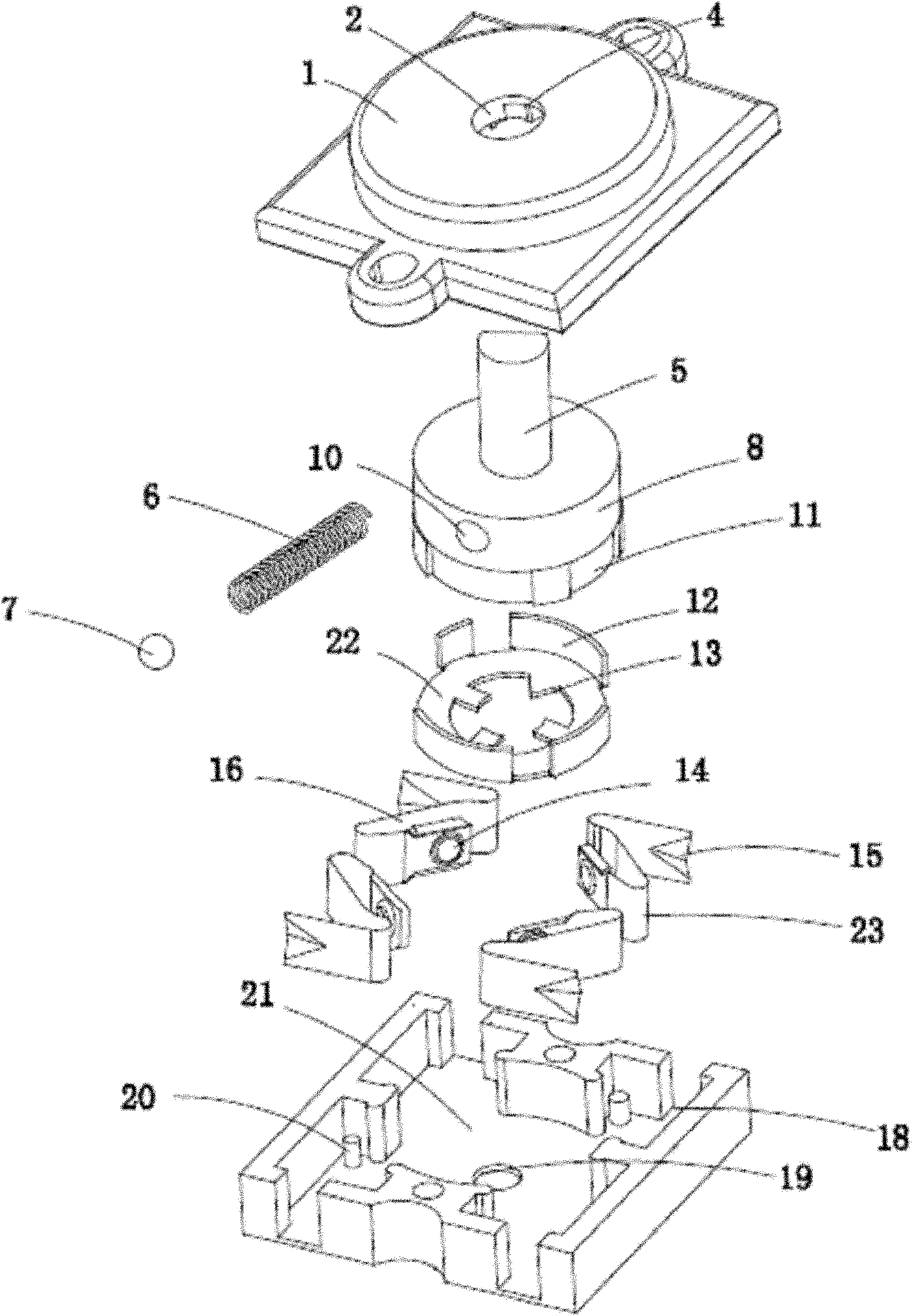
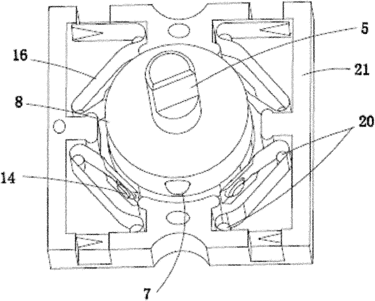
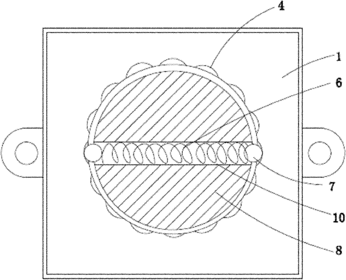
[0019] Such as figure 1 and figure 2 As shown, a 22.5-degree square rotary switch provided in this embodiment includes a cover 1, a knob handle 5, a movable contact piece 22, a reed 16 and a bottom case 21, and a knob seat 8 on the knob handle 5, and a knob seat 8 There is a moving contact slot 11, and the moving contact 22 is provided with a moving contact boss 13 and a moving contact pin 12. The moving contact 22 is mounted on the knob seat 8 and fixed by the moving contact boss 13. , the conductive foot 12 of the movable contact is snapped into the groove 11 of the movable contact, the reed 16 is fixed by the reed fixing pin 20 and arranged in the bottom case 21, and four axially symmetrical reeds 16 are arranged in the bottom case 21 , each reed 16 is provided with a silver contact 14, and each silver contact 14 cooperates with the conductive foot 12 of the movable contact piece; Spring 6, steel balls 7 are provided at both ends of spring 6; knob hole 2 is provided at t...

Embodiment 2

[0020] Such as Figure 5 As shown, the 22.5-degree square rotary switch provided in this embodiment is different from Embodiment 1 in that a limiting boss 9 is provided on the knob seat 8, and the limiting boss 9 fixes the assembly position of the knob seat 8 and the cover 1 and rotation limits.

Embodiment 3

[0022] Such as Figure 4 As shown, a 22.5-degree square rotary switch provided in this embodiment is different from Embodiments 1 and 2 in that a reed wiring groove 15 can be provided on the reed 16, and the reed wiring groove 15 is connected to the bottom shell 21. Wiring notch 18 corresponds, to facilitate external wiring.


PUM


Abstract

The invention discloses a 22.5-degree square rotary switch which comprises a cover, a knob handle, a movable contact spring, a reed and a back shell, wherein a knob seat is arranged on the knob handle, and a movable contact spring clamping slot is arranged on the knob seat; a movable contact spring boss and a movable contact spring conducting pin are arranged on the movable contact spring, and the movable contact spring is arranged on the knob seat and fixed through the movable contact spring boss; the movable contact spring conducting pin is clamped into the movable contact spring clamping slot; the reed is fixed through a reed fixing pin and arranged in the back shell; the side face of the knob seat is provided with a through spring hole, a spring is arranged in the spring hole, and both ends of the spring are respectively provided with a steel ball; an inner tooth slot equally divided into sixteen parts is arranged in the cover; and the positions of the steel balls correspond to the inner tooth slot. When the 22.5-degree square rotary switch is rotated, applied force is low, and gears are clear, thus the persistent energization of heavy current can be guaranteed; and the requirements on 22.5-degree gear rotation and the actual use of a multi-gear high-power small warmer are met.

Description

technical field [0001] The invention belongs to the technical field of electrical switches, in particular to a 22.5-degree square rotary switch used in small heaters requiring multiple gears and high power. Background technique [0002] The existing rotary switches basically use the reeds to directly contact the electricity, without silver contacts, and it is difficult to ensure a good contact state between the reeds, which cannot meet the requirements of high power. In particular, the rotation angle of the knob is too large. Can not satisfy the needs of multi-gear, from the actual use demand of those multi-gear, high-power small-sized heaters, can't meet, so it is necessary to improve the rotary switch of the prior art. Contents of the invention [0003] The object of the present invention is to provide a 22.5-degree square rotary switch with multiple gears, clear gears, reliable contact, high heater power and wide application range in order to solve the above-mentioned d...

Claims


Application Information

Patent Timeline
Patent Type & Authority Applications(China)
IPC IPC(8): H01H19/03H01H19/08H01H19/10H01H19/14
Inventor 林相如
Owner NINGBO JIALIN ELECTRONICS
Why Eureka
Try Eureka