Cooling trough

A technology for cooling water tank and water tank body, which is applied in the directions of grease/oily substance/float removal device, liquid separation, direct contact heat exchanger, etc. And other issues

Active Publication Date: 2011-05-11
SHANGHAI KINGFA SCI & TECH
View PDF6 Cites 13 Cited by
  • Summary
  • Abstract
  • Description
  • Claims
  • Application Information

AI Technical Summary

Problems solved by technology

[0003] After the material strip 10' is pressed into the water tank body 1' by the bead wheel 8', it contacts and cools with the water on the upper part of the water tank body 1', so that the temperature of the water on the upper part of the water tank body 1' rises; The slot hole 321' flows into the water tank body 1', and the continuously injected cold water can only flow along the bottom of the water tank body 1', causing the water temperature at the upper part of the water tank body 1' to be significantly higher than the water temperature at the bottom, which affects the cooling effect of the strip 10'
Since the sewage collection outlet 5' is set at the bottom of the sink body 1', the injected cold water will flow away directly from the sewage collection outlet 5' if it is not fully used, wasting resources
In the prior art, during the cooling process of the material strip 10', impurity floating objects 11' will be generated, which will adhere to the material strip 10' and cannot be collected, which will affect the product quality

Method used


Image

  • Cooling trough
  • Cooling trough
  • Cooling trough

Examples


Embodiment Construction

[0021] The specific embodiments of the present invention will be described below in conjunction with the accompanying drawings.

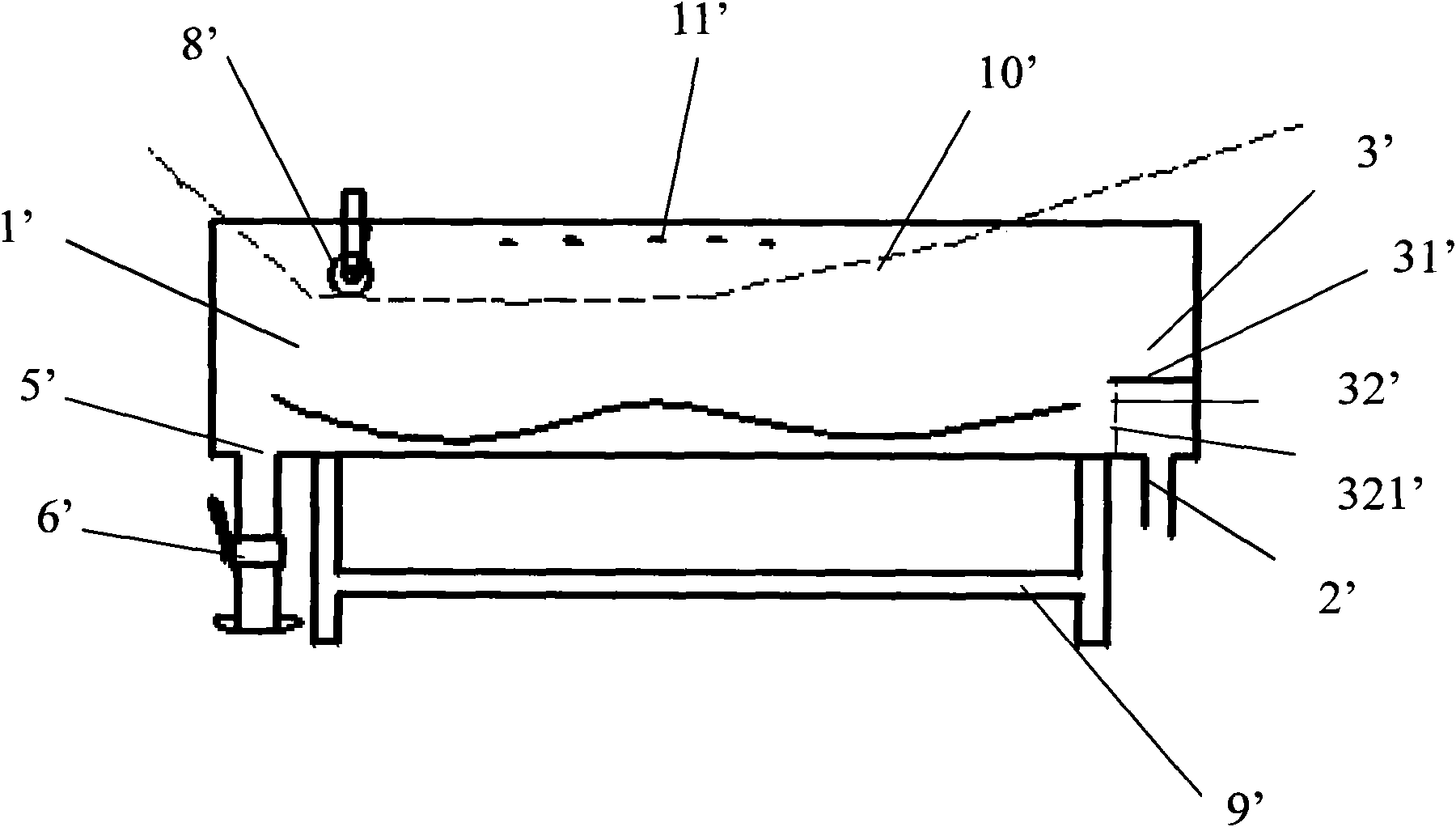
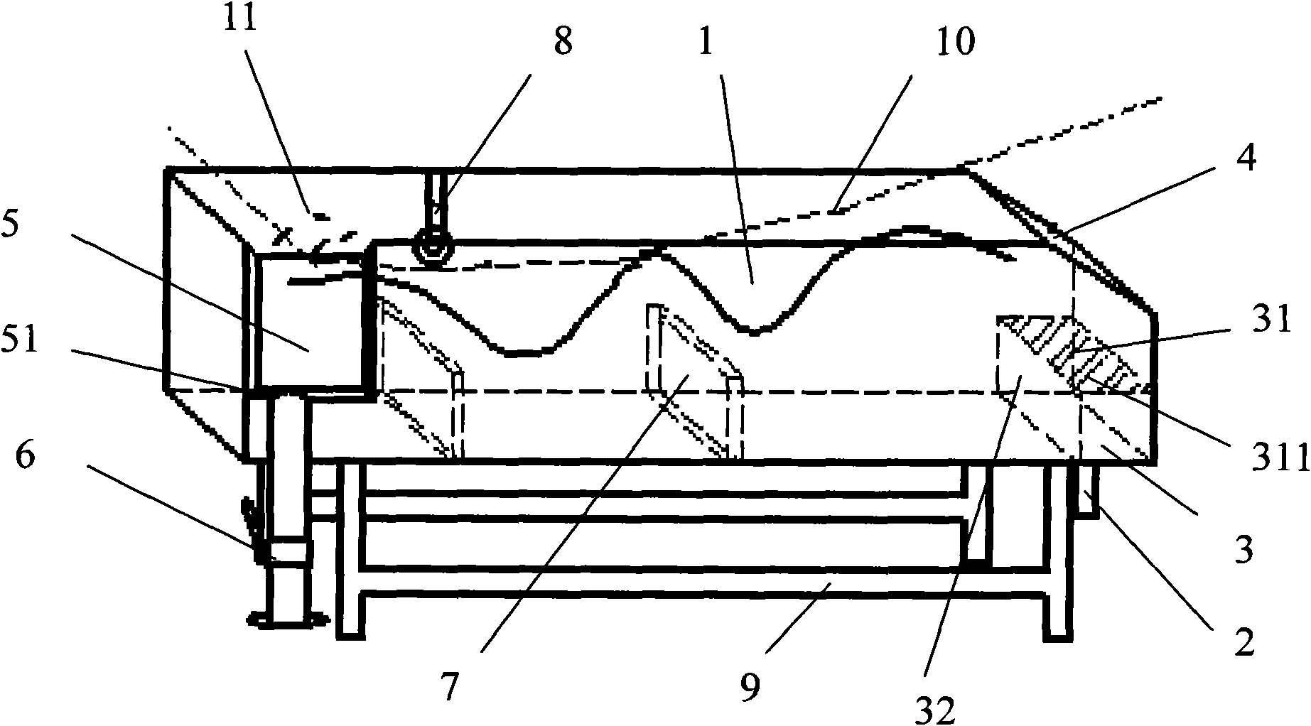
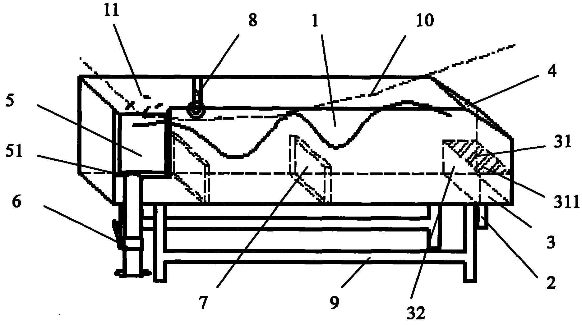
[0022] See figure 2 As shown, the cooling water tank of the present invention includes a water tank body 1, a bracket 9, a water inlet 2, a sewage collection outlet 5, a drain valve 6, a buffer plate 3, a batten wheel 8, and a water flow baffle.

[0023] The bracket 9 is arranged below the sink body 1 to support the sink body 1 . The batten wheel 8 is arranged on the top of the tank body 1 . The water inlet 2 is arranged at the bottom of one end of the sink body 1 .

[0024] The buffer plate 3 is arranged above the water inlet 2 at the bottom of the tank body 1; the buffer plate 3 includes a top plate 31 provided with a plurality of slot holes 311 and a closed side plate 32, the top plate 31 and the side plate 32 form a right angle; the side plate 32 is vertically arranged At the bottom of the sink body 1 ; the top plate 31 is arranged above the...


PUM


Abstract

The invention relates to a cooling trough, which comprises a trough body, a water inlet at the bottom of the trough body, a buffer plate above the water inlet, and a batten wheel at the top of the trough body. The cooling trough is characterized by also comprising a plurality of vertical baffle plates at the bottom of the trough body, an oblique baffle plate arranged above the corresponding trough body of the water inlet, and a sewage collection and drainage port on the lateral surface of the upper part of the trough body. The opening of the buffer plate is changed into a top plate opening, the cooling trough is provided with the oblique baffle plate and the plurality of parallel vertical baffle plates at the bottom, and the sewage collection and drainage port is formed on the lateral surface of the upper part of the trough body, so the water flow direction in the trough body is changed, the water at the upper part and the bottom of the trough body is uniformly mixed, and consistency of water temperature is kept. The sewage collection and drainage port is formed on the lateral surface of the upper part of the trough body, so that the water on the surface of the trough body can flow during drainage to drive the floating objects on the water surface to flow to the sewage collection and drainage port; and meanwhile, a filter screen is arranged for collecting the accumulated floating impurities.

Description

technical field [0001] The invention relates to a cooling water tank, in particular to a cooling water tank with changed water flow direction. Background technique [0002] See figure 1 As shown, the cooling water tank used in the prior art includes a tank body 1 ', a support 9 ', a water inlet 2 ', a sewage collection outlet 5 ', a drain valve 6 ', a buffer plate 3 ', and a batten wheel 8 '. The tank body 1' is set on the bracket 9', the batten wheel 8' is set on the top of the tank body 1'; the water inlet 2' and the sewage collection outlet 5' are respectively set at both ends of the bottom of the tank body 1', and the drain valve 6' Set on the outlet pipe below the sewage collection outlet 5'; the buffer plate 3' includes a top plate 31' and a side plate 32' that are at right angles to each other, and the top plate 31' is set above the water inlet 2' and perpendicular to the side of the tank body 1' Connection; the side plate 32' is vertically arranged at the bottom of...

Claims


Application Information

Patent Timeline
Patent Type & Authority Applications(China)
IPC IPC(8): F28C3/00C02F1/40
Inventor 吕卡利罗李波
Owner SHANGHAI KINGFA SCI & TECH
Why Eureka
Try Eureka