
Device comprising rigid connecting bars for the conducting connection of first to second busbars
A technology of conductive connection and connection device, which is applied in the field of devices with rigid connection rails that electrically connect the first and second conductive rails, and can solve the problems of connection troubles and the like
- Summary
- Abstract
- Description
- Claims
- Application Information
AI Technical Summary
Problems solved by technology
Method used
Image

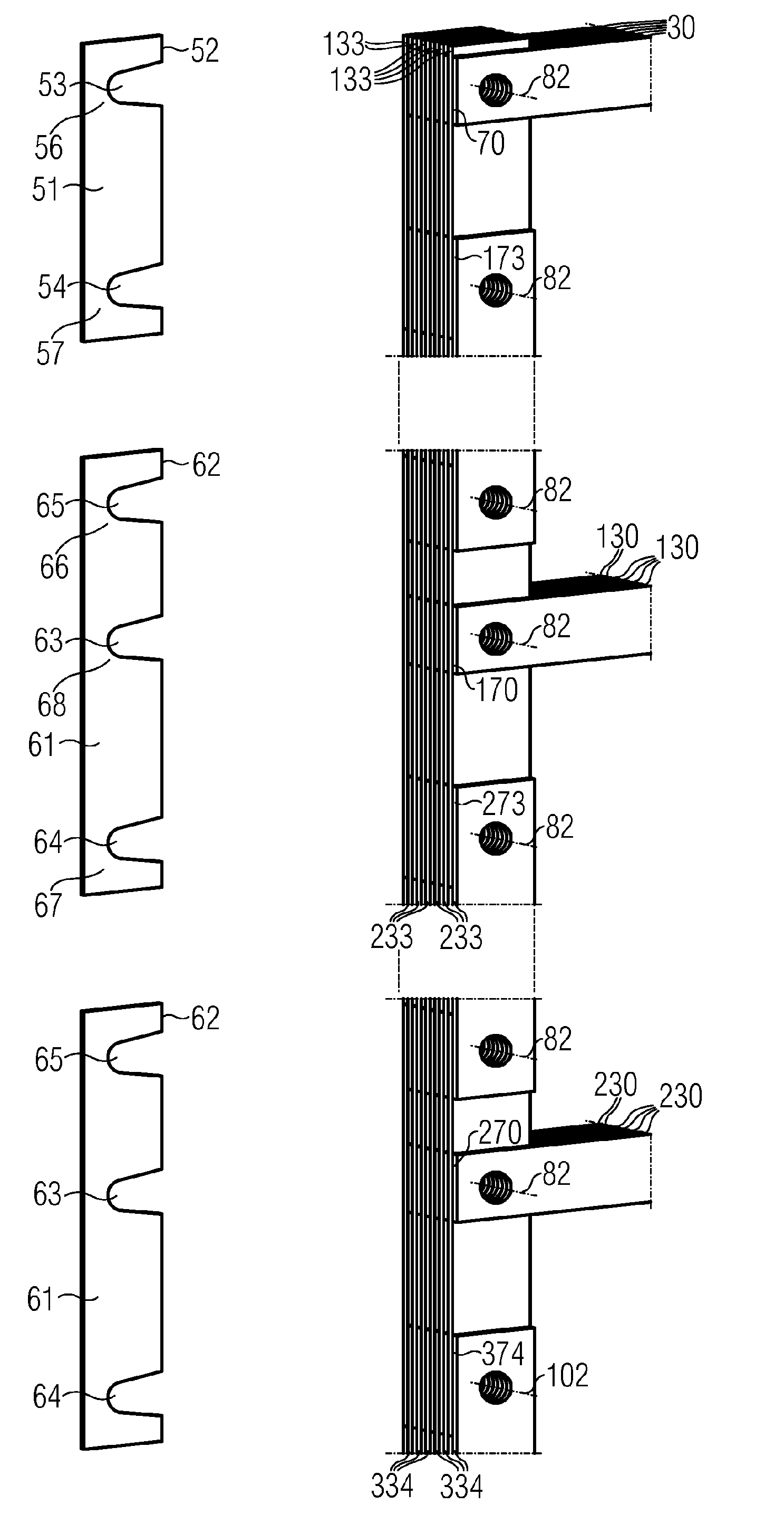
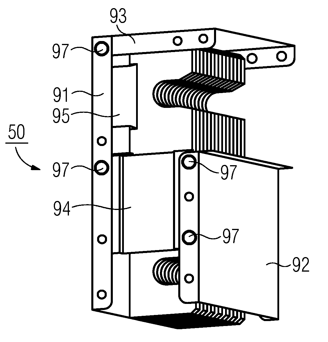
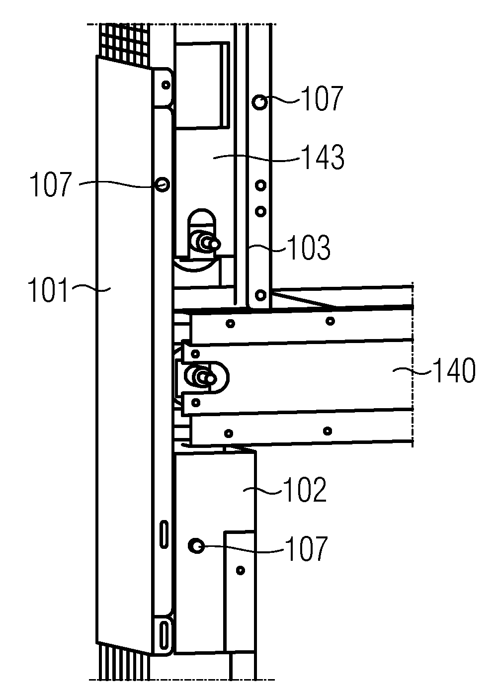
Examples
Embodiment Construction
[0026] exist figure 1 The wind energy installation 1 shown schematically in the center comprises a tower 2 with a foundation 3 , a nacelle 4 mounted rotatably at the top of the tower, and a power module 5 arranged at the base of the tower.
[0027] Arranged within the nacelle 4 is a rotor with rotor blades 6 mounted rotatably about a horizontal axis, as well as a generator 7 . The rotor is set into rotation by the wind force acting on the rotor blades 6 and drives a generator 7 for generating electrical energy.
[0028] In order to transfer the electrical energy generated by the generator 7 to the power module 5 (which has different electrical units), in the inner space 8 of the tower 2 on the walls there are conductor rails 10 arranged with fixing elements 9, which are adjacent The joints of the tower sections are connected with flexible connecting rails. These conductor rails are electrically conductive and are electrically connected via cables 11 to the generator and via ...
PUM
 Abstract
Description
Claims
Application Information