Kitchen appliance having tool drawer

A technology for kitchen equipment and drawers, applied in the directions of drawers, kitchen utensils, home utensils, etc., can solve problems such as high cost production steps and achieve the effect of reliable connection

Active Publication Date: 2012-04-18
BSH BOSCH & SIEMENS HAUSGERAETE GMBH
View PDF5 Cites 2 Cited by
  • Summary
  • Abstract
  • Description
  • Claims
  • Application Information

AI Technical Summary

Problems solved by technology

The use of hinges has proven costly and the production process requires a large number of additional production steps

Method used


Image

  • Kitchen appliance having tool drawer
  • Kitchen appliance having tool drawer
  • Kitchen appliance having tool drawer

Examples


Embodiment approach

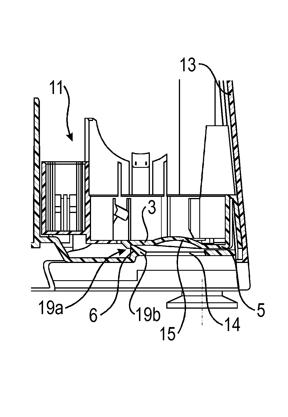
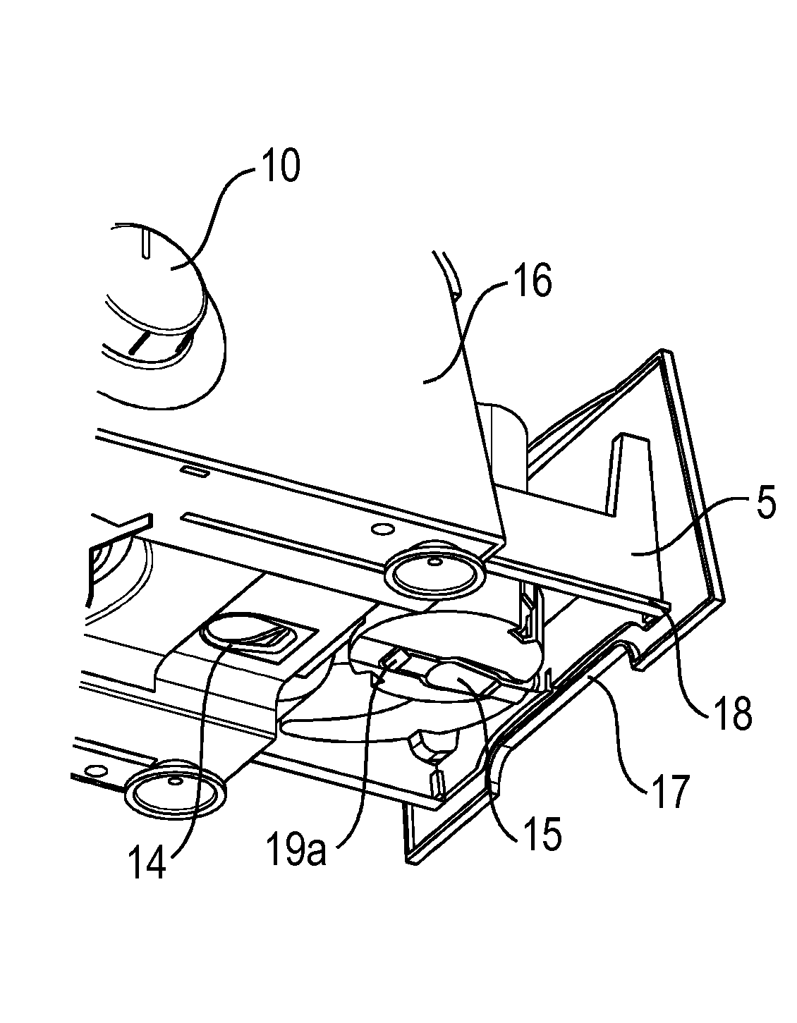
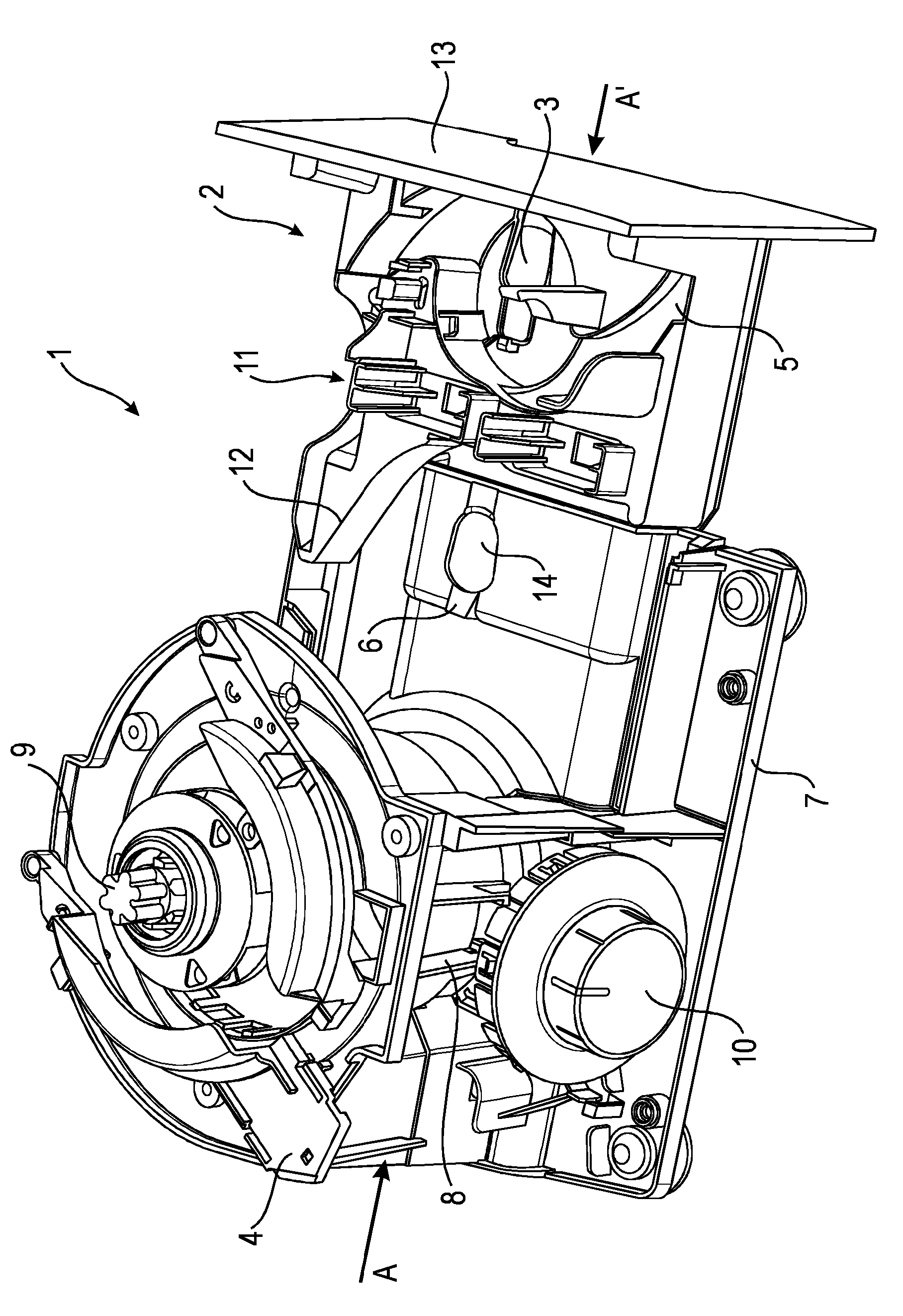
[0034] The functional parts of the kitchen appliance 1 are arranged above the housing part 7 of the kitchen appliance 1 and are then covered by means of a cover in order to prevent contamination or injury to the user. According to one specific embodiment, the housing part 7 and the cover are produced as separate components, but it is also possible to realize the integral construction of the two components in one process step. The housing part 7 , the lid and the drawer 2 can be realized by means of injection molding from a plastic material which has proven to be inexpensive and durable. The tool drawer 2 must be designed in such a way that on the one hand it can receive all tools for operating the kitchen appliance 1 and on the other hand it can make full use of the limited space available above the housing part 7 of the kitchen appliance 1 .

[0035] The tool drawer has various recesses 11 for receiving tools of the kitchen appliance. Various tools can be arranged inside the...


PUM


Abstract

The present invention relates to a kitchen appliance having a tool drawer, wherein the kitchen appliance comprises at least one locking means for locking the tool drawer, wherein the locking device is arranged in a bottom of the tool drawer and in a locked state of the tool drawer engages with a counter means on a housing part of the kitchen appliance.

Description

technical field [0001] The invention relates to a kitchen appliance with a tool drawer, wherein the kitchen appliance has at least one latch for locking the tool drawer. Background technique [0002] Often drawers on kitchen equipment are locked with elastic elements. In the installed position, the drawer is held in place by means of a resilient element, so that it cannot be opened without using a certain amount of force. When transporting kitchen equipment, for example, it should be ensured that drawers cannot be opened unintentionally. The drawers typically contain sharp tools such as shredder knives, abrasive debris, and the like. These tools can cause injury to the user when the drawer opens uncontrollably. [0003] It is also known that accessories for kitchen appliances can be accommodated in a housing closed by a cover. The cover is hingedly mounted to the housing so that the accessory is accessible to the user. Such a device is disclosed in US 4 733 827 . DE 60...

Claims


Application Information

Patent Timeline
Patent Type & Authority Applications(China)
IPC IPC(8): A47J43/07A47B88/04
CPCA47J2043/0738A47J43/0716
Inventor J.佩塞克P.科瓦西克D.鲁德茨
Owner BSH BOSCH & SIEMENS HAUSGERAETE GMBH
Why Eureka
Try Eureka