Network line interface

A network cable interface and main body technology, which is applied in the field of network cables, can solve problems such as increasing the difficulty of troubleshooting, network transmission interruption, and limited shrapnel protection, and achieve the effect of improving connectivity and use security

Active Publication Date: 2012-08-15
YONG TAI ELECTRONICSDONGGUAN LTD
View PDF5 Cites 3 Cited by
  • Summary
  • Abstract
  • Description
  • Claims
  • Application Information

AI Technical Summary

Problems solved by technology

The current network cable interface is equipped with a shrapnel protection body with a thin arc-shaped structure. However, the protection of the shrapnel by using the shrapnel protection body is very limited, and the shrapnel is easy to be caught by other objects or the shrapnel protection body is pressed by mistake. The interface can easily slide out from the mat

Method used


Image

  • Network line interface
  • Network line interface
  • Network line interface

Examples


Embodiment 1

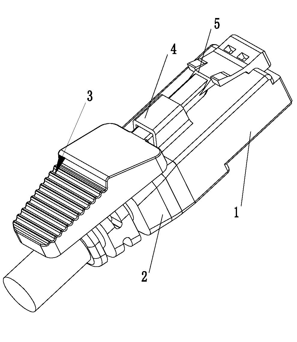
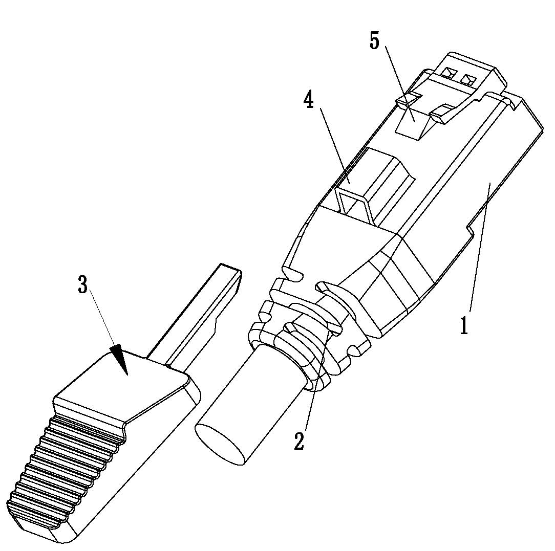
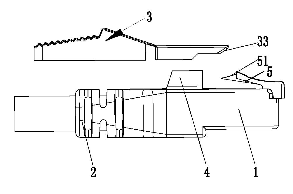
[0043] One of the specific implementations of a network cable interface of the present invention, such as Figure 1 to Figure 6 As shown, it includes a plug main body 1 and an outer mold 2, wherein the front end of the plug main body 1 is provided with a short elastic piece 5, and the rear end of the plug main body 1 protrudes upwards to form a limiting through groove 4. The network cable interface 100 is provided with a push element 3 that is movably matched with it, and the push element 3 passes through the limiting channel 4 and pushes and fits with the short elastic piece 5 .

[0044] The improvement of the present invention is that the shrapnel protector of the network cable interface 100 in the prior art is cancelled, and the shrapnel of the prior art is set as a short shrapnel 5, and the pushing element 3 with the key function and the short shrapnel 5 are pushed Press fit to realize the disconnection between the network cable interface 100 and the plug interface 200, an...

Embodiment 2

[0052] The second specific implementation mode of a network cable interface of the present invention, as Figure 7 to Figure 11 As shown, the main technical solution of this embodiment is the same as that of Embodiment 1, and the features not explained in this embodiment adopt the explanation in Embodiment 1, and will not be repeated here, and are described in Figure 7 to Figure 11 neutralize Figure 1 to Figure 6 The same components are given the same reference numerals. The difference between this embodiment and Embodiment 1 is that the pushing body 32 is provided with a groove 321 , and the inner wall of the limiting channel 4 is provided with a protruding strip 41 that is slidingly fitted with the groove 321 . After the groove 321 is added on the push element, the push element 3 with the key function is special and specific, so that there is not enough space and angle in the limiting through groove 4 that cooperates with it, thereby avoiding the use of a rectangular bar....

Embodiment 3

[0056] The third specific embodiment of a network cable interface of the present invention is as follows: Figure 7 to Figure 11 As shown, the main technical solutions of this embodiment are the same as those of Embodiment 1, and the features not explained in this embodiment are explained in Embodiment 1, and will not be repeated here. The difference between this embodiment and Embodiment 1 is that the two sides of the pushing body 32 are respectively provided with locking points 322 that are interference fit with the limiting channel 4 . Adding a clamping point 322 is convenient for fixing the pushing element 3, and it is fixed when the pushing element 3 does not need to be pulled out.


PUM


Abstract

The invention relates to a network line interface which comprises a plug main body and an external model, wherein a short elastic sheet is arranged at the front end part of the plug main body, and a limiting through slot is formed at the rear end part of the plug main body by upward bulging. The network line interface is provided with a pushing element which is movably matched with the network line interface, wherein the pushing element penetrates through the limiting through slot and is matched with the short elastic sheet in a pushing-pressing manner. Compared with the prior art, the network line interface provided by the invention has the advantages that an elastic sheet protector of the network line interface in the prior art is cancelled, an elastic sheet in the prior art is replaced by the short elastic sheet, and the cut-off between the network line interface and a butting interface is realized through the pushing-pressing matching between the pushing element with a key function and the short elastic sheet. According to the network line interface, the condition that the short elastic sheet easily slides out of the butting interface because the short elastic sheet is touched by an external force can be avoided, and the connectivity and service safety of a network can also be improved.

Description

technical field [0001] The invention relates to the technical field of network cables, in particular to a network cable interface. Background technique [0002] With the development of the network, the network cable interface has been widely used in the computer room to connect with servers, switches and other equipment. [0003] The structure of the network cable interface in the prior art usually includes a plug body and an outer mold, wherein the plug body is provided with shrapnel, the front end of the outer mold is provided with a shrapnel protection body, the rear end of the outer mold is formed with a net tail, and the outer mold It is formed on the rear end of the plug body by injection molding. The current network cable interface is equipped with a shrapnel protection body with a thin arc-shaped structure. However, the protection of the shrapnel by using the shrapnel protection body is very limited, and the shrapnel is easy to be caught by other objects or the shra...

Claims


Application Information

Patent Timeline
IPC IPC(8): H01R13/629H01R13/639
Inventor 许庆仁
Owner YONG TAI ELECTRONICSDONGGUAN LTD
Why Eureka
Try Eureka