Current detection method and power detection circuit

A current detection circuit and current detection technology, applied in the field of communication, can solve the problems of current detection accuracy limitation, high cost, large heat generation, etc., and achieve the effect of reducing requirements, reducing heat generation, and reducing limitations

Inactive Publication Date: 2013-07-24
HUAWEI TECH CO LTD
View PDF5 Cites 5 Cited by
  • Summary
  • Abstract
  • Description
  • Claims
  • Application Information

AI Technical Summary

Problems solved by technology

[0003] However, when using a shunt for current detection, in order to ensure the detection accuracy, it is necessary to configure a high-precision shunt with standard specifications. The requirements for the shunt are relatively strict, so the accuracy of current detection is greatly limited. The shunt will also bring about the problems of high heat generation and high cost

Method used


Image

  • Current detection method and power detection circuit
  • Current detection method and power detection circuit
  • Current detection method and power detection circuit

Examples


Embodiment Construction

[0039] In order to enable those skilled in the art to better understand the technical solutions in the embodiments of the present invention, and to make the above-mentioned purposes, features and advantages of the embodiments of the present invention more obvious and understandable, the following describes the technical solutions in the embodiments of the present invention in conjunction with the accompanying drawings For further detailed explanation.

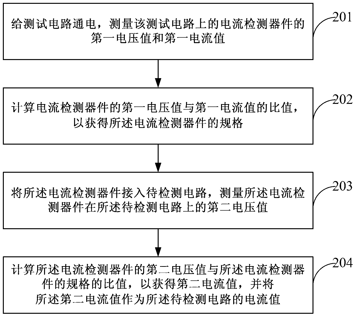
[0040] see figure 2 , is a flowchart of a current detection method according to an embodiment of the present invention.

[0041] The method can include:

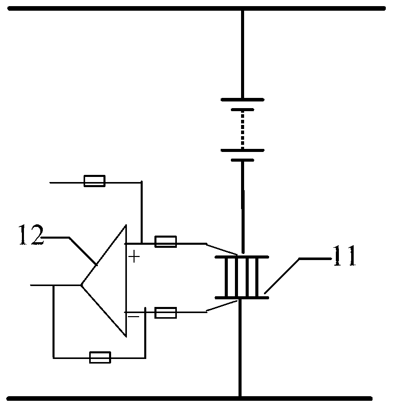
[0042] Step 201, power on a test circuit, and measure a first voltage value and a first current value of a current detection device on the test circuit.

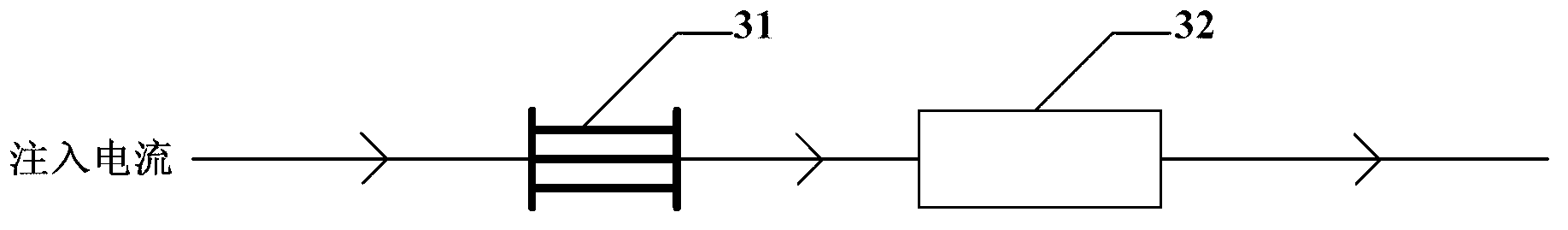
[0043] A current detection device is connected in series in the test circuit, and the test circuit is used to detect the specification of the current detection device. After the specification of the current detection dev...


PUM


Abstract

The invention discloses a current detection method and a power detection circuit. The current detection method comprises the following steps: S1, powering a detection circuit on, and measuring a first voltage value and a first current value of a current detection component on the detection circuit; S2, calculating the ratio of the first voltage value and the first current value of the current detection component to obtain a specification of the current detection component; S3, connecting the current detection component to a circuit to be detected, and measuring a second voltage value of the current detection component on the circuit to be detected; S4, calculating the ratio of the second voltage value and the specification of the current detection component to obtain a second current value, and using the second current value as a current value of the circuit to be detected. By means of the current detection method, high-accuracy shunt is not needed, requirements on current detection components are reduced, limits on current detection are reduced, and the cost of current detection is lowered.

Description

technical field [0001] The invention relates to the field of communication technology, in particular to a current detection method and a power supply detection circuit. Background technique [0002] At present, shunts or Hall sensors are usually used to detect the load current and battery current in the power system. Among them, the shunt is a precise resistor with small resistance that can pass a large current. When the current flows through the shunt, a voltage of millivolt level will appear at both ends of the shunt, so after measuring this voltage , and then convert this voltage into current, and the measurement of large current is completed. E.g figure 1 As shown, by connecting the shunt 11 in series in the circuit, and then using a high-precision operational amplifier 12 to realize the detection of the power supply current by means of a differential detection method. [0003] However, when using a shunt for current detection, in order to ensure the detection accurac...

Claims


Application Information

Patent Timeline
Patent Type & Authority Applications(China)
IPC IPC(8): G01R19/00G01R31/40
Inventor 杨靖尹国华魏庆环
Owner HUAWEI TECH CO LTD
Why Eureka
Try Eureka