Hoisting device

A technology for hoisting devices, masts, applied in the direction of cranes, etc.

Inactive Publication Date: 2014-02-19
SHANGHAI INSTALLATION ENG GRP
View PDF6 Cites 2 Cited by
  • Summary
  • Abstract
  • Description
  • Claims
  • Application Information

AI Technical Summary

Problems solved by technology

[0005] The purpose of the present invention is to provide a hoisting device to solve the problem that the traditional hoisting device cannot be operated in a narrow place, expand the hoisting space of the hoisting device, so as to meet the hoisting requirements in a narrow place

Method used


Image

  • Hoisting device
  • Hoisting device

Examples


Embodiment Construction
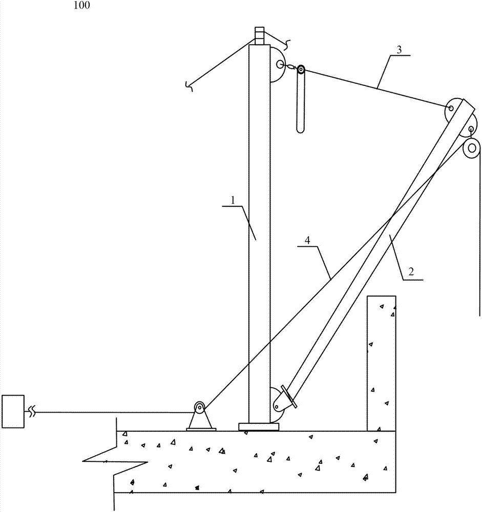
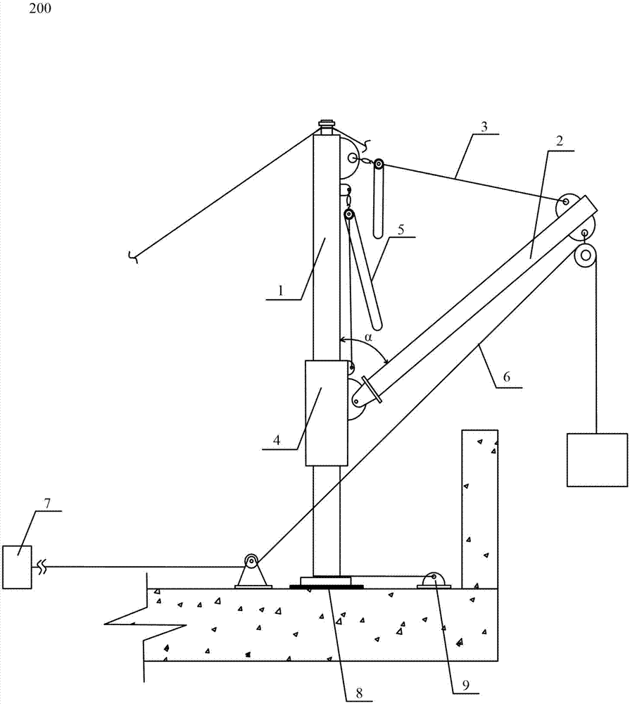
[0015] The core idea of ​​the present invention is to set a sliding motor nest and a chain block on the main mast, and change the position of the sliding motor nest on the main mast through the chain hoist, so as to change the position of the auxiliary pole hinged with the sliding motor nest , so that the position of the sub-rod can vary in a larger range, so as to avoid the sub-rod from being blocked by obstacles around the building, and make the hoisting range of the hoisting system connected with the sub-rod larger to meet the needs of use in narrow places.

[0016] The hoisting device proposed by the present invention will be further described in detail below in conjunction with the accompanying drawings and specific embodiments. Advantages and features of the present invention will be apparent from the following description and claims. It should be noted that all the drawings are in a very simplified form and use imprecise scales, and are only used to facilitate and clear...


PUM


Abstract

The invention provides a hoisting device for solving the problem that an existing hoisting device can not operate in a narrow place. The hoisting device comprises a main mast, a subsidiary rod, an amplitude variation part, a slip flexible nest and a chain block, wherein the slip flexible nest is sleeved on the main mast, and can slip along the main mast; the chain block is fixed at one end of the main mast and is connected with the slip flexible nest through a rope; one end of the subsidiary rod is hinged with the slip flexible nest; the amplitude variation part connects the other end of the subsidiary rod with one end of the main mast. By adopting the hoisting device, the subsidiary rod can be prevented from being blocked by obstacles around buildings, thereby achieving the aim of expanding the hoisting range.

Description

technical field [0001] The invention relates to the technical field of building hoisting, in particular to a hoisting device. Background technique [0002] With the acceleration of the urbanization process and the rapid development of the modern construction industry, the demand for the installation of construction equipment in the construction industry has also increased, and the precision requirements for the installation of construction equipment have also become higher and higher. Typically, the construction equipment is hoisted and installed using a hoisting device. [0003] Such as figure 1 As shown, a conventional hoisting device 100 includes a main mast 1 , an auxiliary mast 2 , luffing 3 and a main hoisting system 4 . Among them, one end of the main mast 1 is fixed on the building, one end of the auxiliary mast 2 is hinged with one end of the main mast 1, and the luffing 3 connects the other end of the main mast 1 with the other end of the auxiliary mast 2, and th...

Claims


Application Information

Patent Timeline
IPC IPC(8): B66C23/62B66C23/82
Inventor 施幼明
Owner SHANGHAI INSTALLATION ENG GRP
Why Eureka
Try Eureka