Automobile sheet metal part punching and blanking device

A technology for punching and blanking of automobile sheet metal parts, applied in the field of stamping equipment, can solve the problems of complex overall structure and easy jamming during operation, and achieve the effect of broad market prospect, reasonable clearance and simple structure

Inactive Publication Date: 2014-05-07
文静
View PDF0 Cites 1 Cited by
  • Summary
  • Abstract
  • Description
  • Claims
  • Application Information

AI Technical Summary

Problems solved by technology

[0002] The current stamping equipment has a complex overall structure and is prone to jamming during operation. In order to improve the product qualification rate, it is necessary to improve the structure and set a reasonable gap between the female and punching male dies

Method used


Image

  • Automobile sheet metal part punching and blanking device

Examples


Embodiment 1

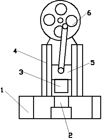
[0013] This embodiment provides a punching and blanking device for automobile sheet metal parts, which is characterized in that: the punching and blanking device for automobile sheet metal parts includes a punching and blanking device base 1 for automobile sheet metal parts, punching Hole female mold 2, punching male mold 3, male mold slideway 4, connecting slider 5, inertia flywheel 6;

[0014] Wherein: the punching die 2 is located in the punching and blanking device base 1 of the automobile sheet metal parts, the male mold slideway 4 is vertically installed on the punching and blanking device base 1 of the automobile sheet metal parts, and the connecting slider 5 is installed on the In the male mold slideway 4, the punching male mold 3 is installed below the connecting slider 5, and the inertia flywheel 6 is connected with the connecting slider 5 by a connecting rod.

[0015] The gap between the punching male die 3 and the edge of the punching female die 3 is 0.5 mm.

Embodiment 2

[0017] This embodiment provides a punching and blanking device for automobile sheet metal parts, which is characterized in that: the punching and blanking device for automobile sheet metal parts includes a punching and blanking device base 1 for automobile sheet metal parts, punching Hole female mold 2, punching male mold 3, male mold slideway 4, connecting slider 5, inertia flywheel 6;

[0018] Wherein: the punching die 2 is located in the punching and blanking device base 1 of the automobile sheet metal parts, the male mold slideway 4 is vertically installed on the punching and blanking device base 1 of the automobile sheet metal parts, and the connecting slider 5 is installed on the In the male mold slideway 4, the punching male mold 3 is installed below the connecting slider 5, and the inertia flywheel 6 is connected with the connecting slider 5 by a connecting rod.

[0019] The gap between the punching male die 3 and the edge of the punching female die 3 is 0.6 mm.

Embodiment 3

[0021] This embodiment provides a punching and blanking device for automobile sheet metal parts, which is characterized in that: the punching and blanking device for automobile sheet metal parts includes a punching and blanking device base 1 for automobile sheet metal parts, punching Hole female mold 2, punching male mold 3, male mold slideway 4, connecting slider 5, inertia flywheel 6;

[0022] Wherein: the punching die 2 is located in the punching and blanking device base 1 of the automobile sheet metal parts, the male mold slideway 4 is vertically installed on the punching and blanking device base 1 of the automobile sheet metal parts, and the connecting slider 5 is installed on the In the male mold slideway 4, the punching male mold 3 is installed below the connecting slider 5, and the inertia flywheel 6 is connected with the connecting slider 5 by a connecting rod.

[0023] The gap between the punching male die 3 and the edge of the punching female die 3 is 0.7 mm.


PUM


Abstract

Disclosed is an automobile sheet metal part punching and blanking device. The automobile sheet metal part punching and blanking device is characterized by automobile sheet metal part punching and blanking device base, a cavity die, a punching terrace die, a terrace die slide, a connecting slider and an inertia fly wheel. The cavity die is arranged inside the automobile sheet metal part punching and blanking device base, the terrace die slide is perpendicularly mounted on the automobile sheet metal part punching and blanking device base, the connecting slider is mounted inside the terrace die slide, and the punching terrace die is mounted at the bottom of the connecting slider, and the intertia fly wheel is connected with the connecting slider through a connecting rod. The automobile sheet metal part punching and blanking device has the advantages of being simple in structure, convenient to use, low in cost, reasonable in the gap between the cavity die and the punching terrace die, stable in operation and wide in market prospect.

Description

technical field [0001] The invention relates to the field of stamping equipment, and in particular provides a punching and blanking device for automobile sheet metal parts. Background technique [0002] The current stamping equipment has a complex overall structure and is prone to jamming during operation. In order to improve the product qualification rate, it is necessary to improve the structure and set a reasonable gap between the female die and the punching male die. Contents of the invention [0003] [0004] The object of the present invention is to improve the qualified rate of products, and especially provides a punching and blanking device for automobile sheet metal parts. [0005] The invention provides a punching and blanking device for automobile sheet metal parts, which is characterized in that: the punching and blanking device for automobile sheet metal parts includes a punching and blanking device base 1 for automobile sheet metal parts, punching Female mo...

Claims


Application Information

Patent Timeline
Patent Type & Authority Applications(China)
IPC IPC(8): B21D37/10
Inventor 文静
Owner 文静
Why Eureka
Try Eureka