An electrostatic induction generator

An electrostatic induction and generator technology, applied in the direction of induction generators, etc., can solve the problems of poor long-distance transmission of direct current, the use of direct current generators is not very common, and the practical significance is not large, so as to avoid the consumption of a large amount of electric energy, the structure is simple, the Long service life effect

Active Publication Date: 2016-05-04
李鹏卓
View PDF5 Cites 0 Cited by
  • Summary
  • Abstract
  • Description
  • Claims
  • Application Information

AI Technical Summary

Problems solved by technology

[0003] The use of DC generators is not very common, and its power generation principle is also electromagnetic induction, so it will also face the problems faced by AC generators, and DC power is not good for long-distance transmission, so it has little practical significance

Method used


Image

  • An electrostatic induction generator
  • An electrostatic induction generator
  • An electrostatic induction generator

Examples


Embodiment 1

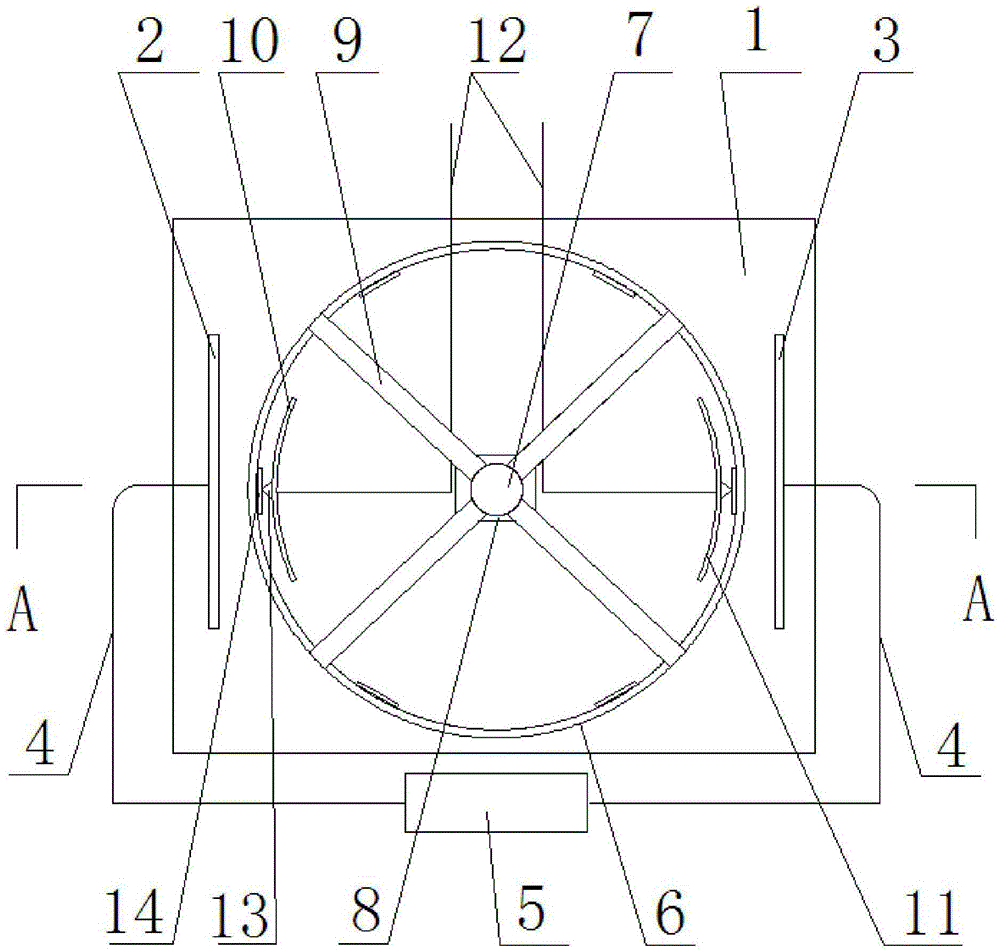
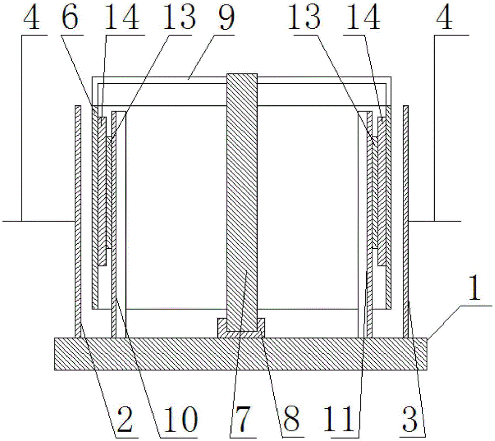
[0023] Such as figure 1 , figure 2 As shown, this embodiment includes an insulating base 1, on which a first metal plate 2 and a second metal plate 3 are vertically arranged, and the first metal plate 2 and the second metal plate 3 The first metal plate 2 is connected to the positive pole of the DC high-voltage power supply 5 through the wire 4, and the second metal plate 3 is connected to the negative pole of the DC high-voltage power supply 5 through the wire 4. The first metal plate 2 and the second An insulating drum 6 is arranged between the metal plates 3, and a central shaft 7 is arranged at the center of the drum 6, and the central shaft 7 is fixed on the base 1 through a bearing seat 8, and the central shaft 7 and The drums 6 are all set up vertically, the bottom end of the central shaft 7 is arranged on the bearing seat 8 on the base 1, and the top end of the central shaft 7 passes through the support 9 and the drum 6 The top end of the drum 6 is fixed, and a gap ...

Embodiment 2

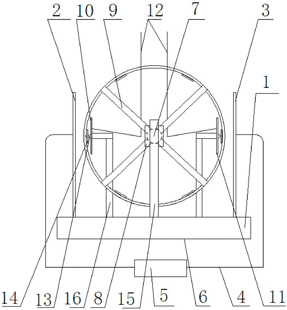
[0026]This embodiment includes an insulated base 1, on which a first metal plate 2 and a second metal plate 3 are vertically arranged, and the first metal plate 2 and the second metal plate 3 are arranged in parallel and opposite each other , the first metal plate 2 is connected to the positive pole of the DC high-voltage power supply 5 through a wire 4, the second metal plate 3 is connected to the negative pole of the DC high-voltage power supply 5 through a wire 4, and the first metal plate 2 and the second metal plate 3 An insulated drum 6 is arranged between them, and a central shaft 7 is arranged at the center of the drum 6, and the central shaft 7 is fixed on the base 1 through a bearing seat 8, and the central shaft 7 and the rotating drum The barrel 6 is arranged horizontally, and both ends of the central shaft 7 are provided with central shaft struts 15, and the bottom ends of the two central shaft struts 15 are fixed on the base 1, and the two central shaft struts 15 ...


PUM


Abstract

The invention relates to an electrostatic induction generator which comprises an insulating generator base. A first metal plate and a second metal plate are vertically arranged on the generator base in parallel, and the first metal plate and the second metal plate are connected with the positive electrode and the negative electrode of a high direct voltage power source through wires respectively, and an insulating revolving drum is arranged between the first metal plate and the second metal plate. A center shaft is arranged in the center of the revolving drum and is fixed to the generator base through a bearing block. The center shaft is fixedly connected with the revolving drum through a support, and the generator base is fixedly provided with a first metal induction block and a second metal induction block. The first metal induction block and the second metal induction block are located in the revolving drum and are fixedly provided with metal contact blocks respectively. The inner wall of the revolving drum is provided with at least one pair of metal sheets which are symmetric about the center of the revolving drum. According to the electrostatic induction generator, an electrostatic induction principle is used for power generation, and the defects of demagnetization caused after a permanent magnet stator is used for a long time and consumption of a large amount of electric energy in the using process of an electromagnet stator are overcome.

Description

technical field [0001] The invention relates to the technical field of generators, in particular to an electrostatic induction generator. Background technique [0002] The current commonly used alternators use the principle of electromagnetic induction to make the conductor cut the magnetic induction line to generate electricity. The biggest disadvantage of this kind of generator is that not only the structure is complicated, but also its power generation efficiency will be greatly reduced as the use time is extended, because the current in the rotor itself is also generating a changing magnetic field, and the long-term existence of this magnetic field, It will cause the permanent magnet on the stator to demagnetize, resulting in lower and lower power generation efficiency. Therefore, the large-scale three-phase alternating generators currently used all use electromagnets on the stator to prevent the efficiency of the generator from decreasing due to stator demagnetization,...

Claims


Application Information

Patent Timeline
Patent Type & Authority Patents(China)
IPC IPC(8): H02N1/06
Inventor 李鹏卓
Owner 李鹏卓
Why Eureka
Try Eureka