

Insulated operating rod
A technology of insulating operating rods and insulating rods, applied in the direction of contact operating parts, etc., can solve the problems of easy corrosion, potential safety hazards, easy loosening of rod heads and insulating rods, etc., and achieve the effect of being easy to carry and not easy to loosen
Inactive Publication Date: 2015-04-08
谢博门
View PDF0 Cites 0 Cited by
- Summary
- Abstract
- Description
- Claims
- Application Information
AI Technical Summary
Problems solved by technology
The head of the traditional insulated operating rod is exposed outside, which is easy to corrode, and the connection between the rod head and the insulating rod is easy to loose, posing a safety hazard
Method used
View moreImage
Smart ImageViewing Examples

Examples
Embodiment Construction
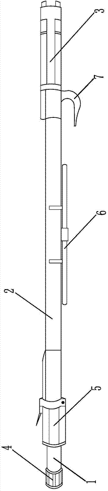
[0009] Such as figure 1 As shown, the present invention consists of a rod head 1, an insulating rod 2 and a handshake 3, and is characterized in that: the head of the rod head 1 is provided with a plug 4, and the bottom is fixed with a hinge 5, and the rod head 1 and the insulating rod The rod 2 is fixedly connected by a hinge 5 , a clamp 6 is provided in the middle of the insulating rod 2 , and a hook 7 is provided at the front end of the handshake 3 .
[0010] Through the above settings, the present invention has clamps 6 and hooks 7, which are convenient for carrying and shelving, and has a plug 4, which can effectively prevent the rod head 1 from being corroded.
Login to View More PUM
 Abstract
The invention discloses an insulated operating rod, which is formed by a rod head, an insulated rod and a handle, and is characterized in that a plug is arranged on the head part of the rod head; a hinge is fixed on the bottom part of the rod head; the rod head is fixedly connected with the insulated rod through the hinge; a fixture is arranged in the middle of the insulated rod; a pothook is arranged on the front end of the handle. Through the arrangement, the plug is arranged, so that the rod head is not easy to corrode, and is durable in use; a connecting part is not easy to loose, so that the insulated operating rod can be operated safely. The insulated operating rod is provided with the fixture and the pothook so as to be convenient to carry.
Description
technical field [0001] The invention relates to an electrical appliance, in particular to an insulating operating rod. Background technique [0002] The insulating operating rod is an insulating tool used to operate live equipment in a short time, such as turning on or off the high-voltage isolating switch, dropping the fuse, etc. The rod head of the traditional insulating operating rod is exposed outside, which is easy to corrode, and the connecting part between the rod head and the insulating rod is easy to loose, posing potential safety hazards. Contents of the invention [0003] The purpose of the present invention is to provide an insulated operating rod that is not easy to corrode, not easy to loosen, easy to carry, safe and durable. [0004] In order to achieve the above object, the present invention consists of a rod head, an insulating rod and a handshake. The head of the rod head is provided with a plug, and the bottom is fixed with a hinge. The rod head...
Claims
Login to View More Application Information
Patent Timeline
 Patent Type & AuthorityApplications(China)
IPC IPC(8): H01H3/02
CPCH01H3/02
Inventor谢博门
Owner谢博门