
Low-torque self-sealing fire hydrant
A low-torque, fire hydrant technology, applied in fire rescue, etc., can solve the problems of easy vibration, water hammer, fire hydrant damage, etc., and achieve the effect of reducing the overall vibration
- Summary
- Abstract
- Description
- Claims
- Application Information
AI Technical Summary
Problems solved by technology
Method used
Image


Examples
Embodiment Construction
[0019] Below, the substantive features and advantages of the present invention will be further described in conjunction with examples, but the present invention is not limited to the listed examples.
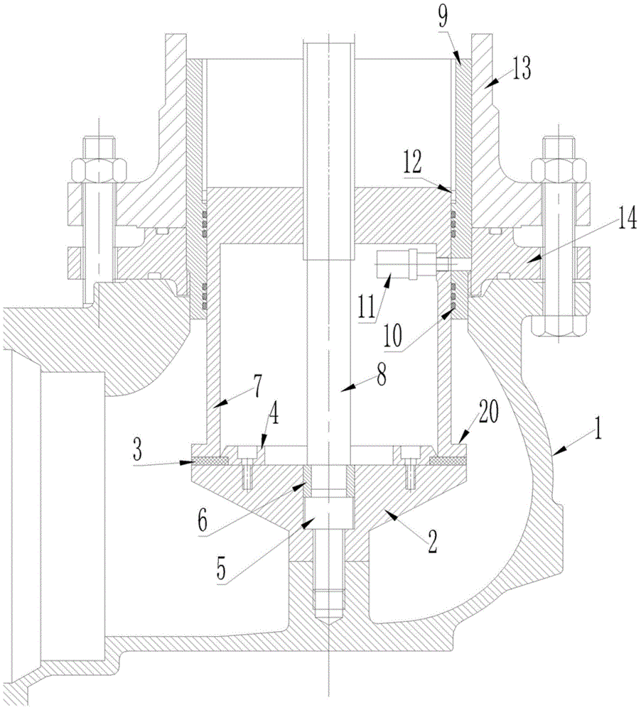
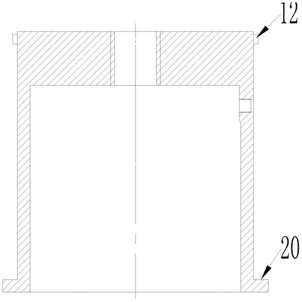
[0020] see Figure 1-4 , a low-torque self-sealing fire hydrant, comprising a plug body, the plug body is provided with a water inlet 1, and a tray 2 is fixedly arranged near the water inlet 1, and a valve shaft 8 is inserted on the tray 2, The valve shaft 8 is connected to the valve seat 7 through threads, the outer side of the valve seat 7 is sleeved in the guide cylinder 9, and the inner wall of the valve seat 7 is equipped with a valve so that the fluid flows from the valve seat 7 to the outside of the valve seat 7. The one-way valve 11, the wall of the guide cylinder 9 is provided with a through hole communicating with the outside, by turning the valve shaft 8 to make the valve seat 7 away from or close to the tray 2 to open or close the water inlet 1, when the When the va...
PUM
 Abstract
Description
Claims
Application Information