Blower

A blower and frame technology, applied in mechanical equipment, machines/engines, liquid fuel engines, etc., can solve the problems of damaged sealing gaskets, easy displacement, damaged sealing gaskets, etc., and achieve the effect of load reduction

Active Publication Date: 2015-06-10
FULTA ELECTRIC MACHINERY CO LTD
View PDF7 Cites 2 Cited by
  • Summary
  • Abstract
  • Description
  • Claims
  • Application Information

AI Technical Summary

Problems solved by technology

As a result, there are disadvantages such as damage to the sealing gasket, damage and easy displacement of the sealing gasket

Method used


Image

  • Blower
  • Blower
  • Blower

Examples


Embodiment Construction

[0043] Embodiment of the invention

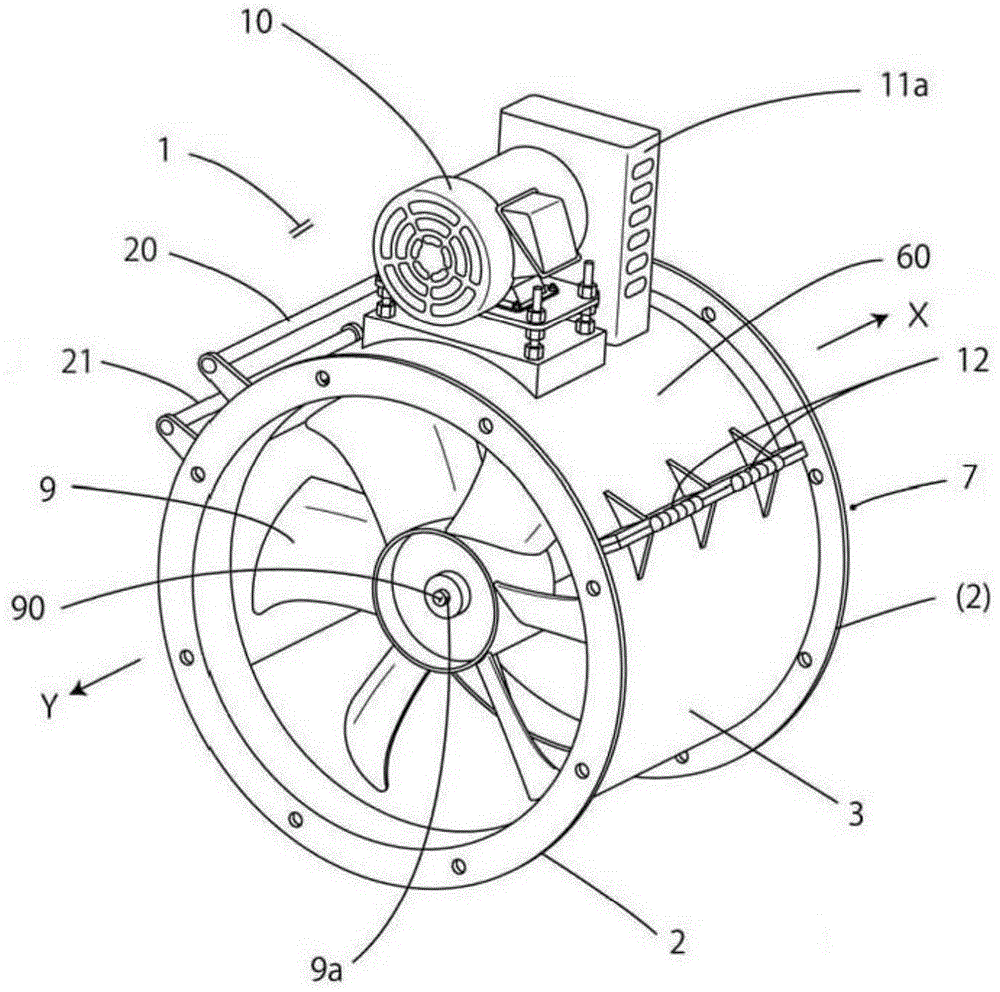
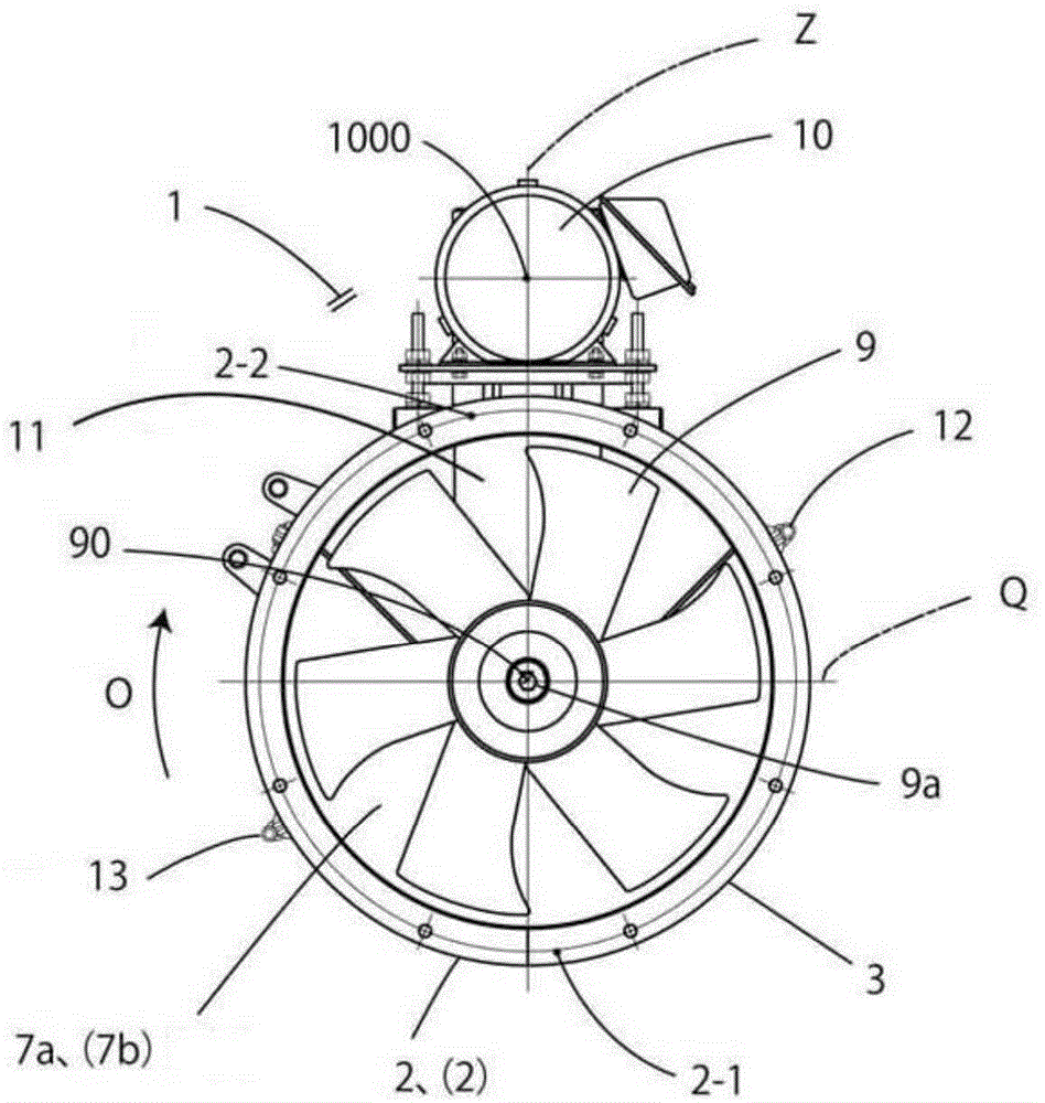
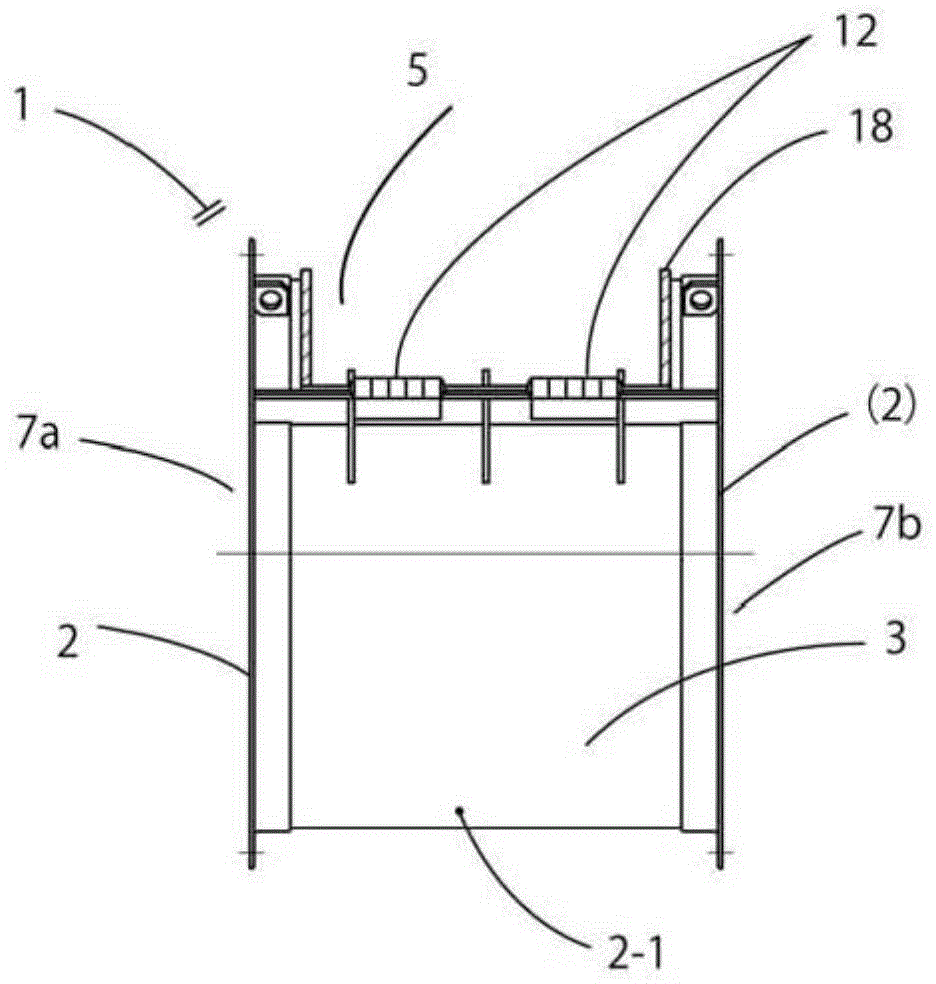
[0044] 1 is a duct fan (a type of blower), such as Figure 1-3 as well as Figure 5 Like the example shown, this duct ventilator 1 comprises the suitable annular frame 2,2 that is arranged in pairs at intervals (only one symbol is taken in the paired example, and only one side is illustrated), and the annular frame 2 The fixed side frame body 3 integrally formed at the bottom of the lower half 2-1 between the ring frames 2 and the cover portion of the upper half 2-2 between the ring frames 2 are freely openable and closed. The frame 7 formed by the movable side frame body 6 that closes the open opening 5 of the upper half 2-2 on the inner side of the ring frame 2 is supported on the movable side frame that is located at the frame 7 with a fastener 8a. The flange-shaped bearing 8 on the pulley cover mentioned later on the body 6 can freely rotate through the shaft 9a arranged at the bearing 8, and the fan 9 arranged on the shaft 9a and a...


PUM


Abstract

In a conventional pipeline blower, a movable side rack of a frame is a starting rack approximately 180-degree structure, and the bottoms of the movable side racks are pivoted to a free end of a fixed side rack and arranged on an outer periphery of the fixed side rack; a start/stop half-circle structure has disadvantages that the movable side rack is closed in front of another free end of the fixed side rack, i.e., part of a sealing pad of an opening portion of an upper portion of a frame annular rack is displaced in a cross side of the periphery direction; the frame has two openings and is formed by the fixed side rack and the movable side racks connecting/disconnecting the fixed side rack; in the frame, a fan arranged in the frame and a blower driving a motor of the fan, at least part of left-right dual-door forms the movable side racks; the bottom end of each movable side rack is pivoted to two free ends of the fixed side rack, wherein a first connecting point (pivot portion) and a second connecting point (pivot portion) are fixed outside the periphery of the fixed side rack, thus protecting sealing pads of the movable side racks.

Description

technical field [0001] The present invention relates to a duct fan between ducts for cooling or drying of products or for supply or exhaust of high temperature air / gas etc. or between ducts for supply or exhaust of air / gas etc. Blowers for duct ventilators, etc. Background technique [0002] In traditional blowers (such as Figure 10-1 In the shown duct fan), the movable side frame body of the frame is a roughly 180-degree (semicircular) structure of the opening and closing frame, and a bottom end side of the movable side frame body is pivotally connected to the fixed side A structure in which one free end side of the frame body is simultaneously provided on the outer peripheral surface of the fixed-side frame body. In the structure of the opening and closing semicircle shape, the movable side frame body is closed in this way, before it is about to close (before touching the other free end side of the fixed side frame body, see Figure 10-2 ), a part of the sealing gasket ...

Claims


Application Information

Patent Timeline
Patent Type & Authority Applications(China)
IPC IPC(8): F04D25/08F04D29/00
CPCF04D25/08F04D29/002F04D29/522
Inventor 古田成广山口一广田中悟日下部圭介
Owner FULTA ELECTRIC MACHINERY CO LTD
Why Eureka
Try Eureka