Device for preventing children from falling from building

A falling down, children's technology, applied in the direction of the fastening device of the wing fan, the operating mechanism of the wing fan, the door/window accessories, etc. Open and other problems, to achieve the effect of low production cost, compact structure and low cost

Active Publication Date: 2015-07-01
真吾(杭州)应急科技有限公司
View PDF11 Cites 2 Cited by
  • Summary
  • Abstract
  • Description
  • Claims
  • Application Information

AI Technical Summary

Problems solved by technology

[0003] In order to solve the above problems, the utility model patent "windows for preventing falling from buildings" (ZL 201420317547.X) controls the rotation of the window frame through the mechanical relationship between the ratchet and the rotating shaft, but the above structure has the following problems: ①It can only be used for inward opening or outward opening Window opening cannot be used for horizontally sliding windows, and teaching building...

Method used


Image

  • Device for preventing children from falling from building
  • Device for preventing children from falling from building
  • Device for preventing children from falling from building

Examples


Embodiment 1

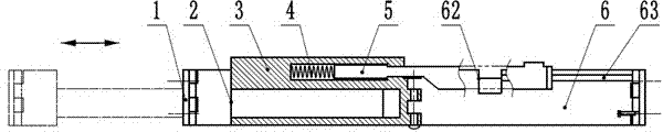
[0039] In embodiment 1, such as Figures 1 to 6 As shown, the locking device 7 is an independent structure made of elastic material, including a horizontal bottom plate and an inverted "V"-shaped first hook body, the front end of the first hook body is connected with the front end of the bottom plate, and the first hook body is connected to the front end of the bottom plate. The rear end of a hook body is located above the second arm plate 6, and the position of the second arm plate 6 is limited by the joint action of the first hook body and the fixed rod 5, so that the second arm plate 6 and the sleeve 3 are kept in the same position. on a horizontal line without bending.

[0040] The exposed end of the fixing rod 5 is provided with one or more connecting devices 52 , the connecting devices 52 are wide at the bottom and narrow at the top, and a protruding edge structure is provided in the middle. The lower part of the clamping device 7 is provided with a slot compatible with...

Embodiment 2

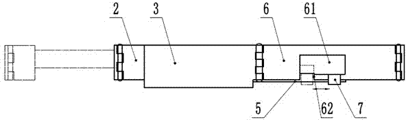
[0045] In embodiment 2, such as Figure 7 , 8 As shown in . Located above the second arm plate 6, the second arm plate 6 is clamped by the lock tongue 91, and the position of the second arm plate 6 is restricted through the joint action of the lock tongue 91 and the fixed rod 5, so that the second arm plate 6 and the sleeve 3 remain on the same level and cannot be bent. After inserting the key, turn the lock cylinder to drive the dead bolt 91 to rotate and the dead bolt 91 can be removed from the top of the second arm plate 6 .

[0046] In addition to the gap 62 in the above basic technical features, the second arm plate 6 is also provided with a broken rod gap 64 adapted to the lock tongue 91, and the broken rod gap 64 is located in the natural state. Just below the dead bolt 91 mentioned above. The second arm plate 6 is provided with a blind hole along the length direction of the second arm plate 6. The opening of the blind hole is located on the side wall of the broken ...

Embodiment 3

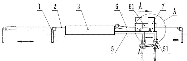
[0050] In embodiment 3, such as Figures 10 to 13 As shown, the locking device is an inverted "V"-shaped second hook body 53, the front end of the second hook body 53 is fixedly connected to the fixed rod 5, and the rear end of the second hook body 53 is located on the second arm. plate 6 above. The position of the second arm plate 6 is limited by the joint action of the second hook body 53 and the fixing rod 5 , so that the second arm plate 6 and the sleeve 3 are kept on the same horizontal line and cannot be bent. The second hook body 53 is made of elastic material.

[0051] The upper surface of the second arm plate 6 is provided with a boss 61, the part where the front side of the boss 61 intersects with the notch 62 and the rear side of the notch 62 are inclined backward and downward, forming a smooth slope 611 together. . A vertical plane 612 perpendicular to the front side is formed at the intersection of the inclined surface 611 part and the non-inclined part of the ...


PUM


Abstract

The invention discloses a device for preventing children from falling from a building, and belongs to the field of a door and window component. The device is characterized by comprising two connecting pieces, a first arm plate, a second arm plate, a sleeve and a fixed rod, wherein one ends of the two connecting pieces are respectively hinged to one ends of the first arm plate and the second arm plate, the other end of the second arm plate is hinged to one end of the sleeve, and the first arm plate is embedded into a hole, away from the hinged end of the sleeve, of an inner opening of the sleeve; one part of the fixed rod is arranged in a hole, facing the hinged end of the sleeve, of the inner opening of the sleeve, and the other part of the fixed rod is exposed; a spring is arranged between the fixed rod and a blind end of the hole; the exposed end of the fixed rod is provided with a jamming device. Compared with the prior art, the device has characteristic that children can be prevented from falling from the building.

Description

technical field [0001] The invention relates to a door and window part, in particular to a device suitable for preventing children from falling from a building. Background technique [0002] The teaching building is densely populated, and the students in primary and secondary schools and kindergartens are young, curious, and weak in self-protection ability, and incidents of falling from windows happen from time to time. Therefore, in order to prevent the above accidents, some teaching places install protective fences on the outside of the windows of the teaching building. However, in the event of a fire or other events that cannot be evacuated from the corridor, the installation of protective fences will delay the rescue speed and even lead to self-rescue failure. In addition, when an emergency occurs in the teaching building, due to the large number of people in the teaching building, it is difficult to evacuate in a short time, and the people on the first floor can escape ...

Claims


Application Information

Patent Timeline
IPC IPC(8): E05C17/02E05B65/00
CPCE05C17/08E05C17/30E05C17/36E05F11/53
Inventor 胡家宁王萍田小燕
Owner 真吾(杭州)应急科技有限公司
Why Eureka
Try Eureka