

Gas filtering device
A filtration device and gas technology, which are applied in the fields of dispersed particle filtration, dispersed particle separation, chemical instruments and methods, etc., can solve the problems of reducing the filtration efficiency of the filter element and increasing the difficulty of backflushing.
- Summary
- Abstract
- Description
- Claims
- Application Information
AI Technical Summary
Problems solved by technology
Method used
Image

Examples
Embodiment Construction
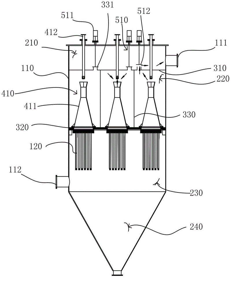
[0014] The gas filtering device of the present invention comprises a filtering device housing 110, and the filtering device housing 110 is sequentially divided into an air outlet chamber 210, an original air chamber 220 and a clean air chamber 230 from top to bottom, and the air outlet chamber 210 and the clean air chamber 230 Separated by a diaphragm 310, the clean air chamber 230 is separated from the original air chamber 220 by an orifice 320, and an ash chamber 240 is also provided below the original air chamber 220, and the ash chamber 240 The lower end is provided with an ash discharge port 241, and the filter device housing 110 is provided with an air outlet 111 communicating with the air outlet chamber 210 and an air inlet 112 communicating with the original air chamber, and three filter element groups are provided below the orifice plate 320 120, the top of each filter element group 120 is provided with a blowback device 410, and the blowback device 410 includes a vent...
PUM
 Abstract
Description
Claims
Application Information