MAANSHAN GELIN MINING & METALLURGY ENVIRONMENTAL PROTECTION EQUIP
View PDF2 Cites 0 Cited by
Summary
Abstract
Description
Claims
Application Information
AI Technical Summary
This helps you quickly interpret patents by identifying the three key elements:
Problems solved by technology
Method used
Benefits of technology
Problems solved by technology
[0005] Aiming at the problems that existing sealing rings have inflexible sealing and are not suitable for frequent relative movement between fixed parts and moving parts, the present invention provides a movable sealing device and its use method, which include an outer ring body, an inner ring body, rubber The sealing ring and the limit rod, the outer ring body and the bearing cover are fixed by bolts, which can meet the demand for a large gap between the pressure roller and the rotating shaft; the inner ring body is equipped with a rubber sealing ring, so that the side of the inner ring body close to the rotating shaft The rotating shaft is in close contact, and the radially opposite sides of the inner ring body are planar structures. The limit rod is set between the planar structure of the inner ring body and the outer ring body. The rubber sealing ring can move horizontally relative to the outer ring body to realize the sealing function
Method used
Image
Click on the blue label to locate the original text in one second.
Reading with bidirectional positioning of images and text.
Examples
Embodiment 1
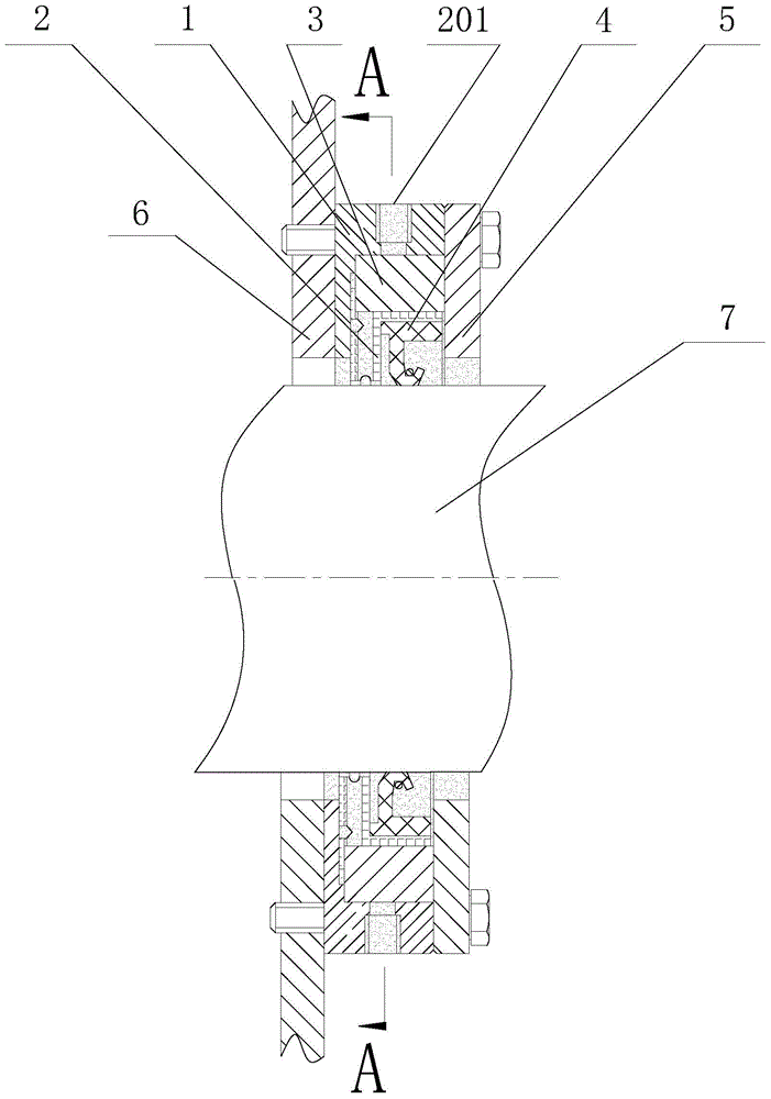
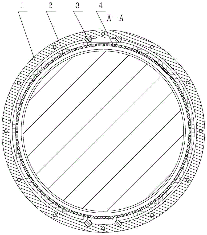
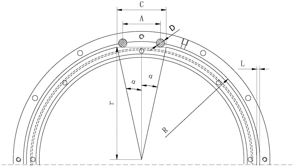
[0032] Such as figure 1 , figure 2 and image 3As shown, a movable sealing device includes an outer ring body 1, an inner ring body 2, a rubber sealing ring 4, a gland 5 and a limit rod 3, and the outer ring body 1 and the inner ring body 2 are both ring-shaped, The cross sections of the outer ring body 1 and the inner ring body 2 are both in the shape of "7", which are divided into vertical planes and horizontal planes; the outer diameter of the outer ring body 1 is 0.2m, the thickness is 35mm, and the inner diameter 2R of the outer ring body 1 is 183mm , the difference 2L between the inner diameter of the outer ring body 1 and the outer diameter of the inner ring body 2 is 5mm, the inner side of the horizontal plane of the outer ring body 1 is provided with an annular groove, and the thickness of the inner ring body 2 is smaller than the annular groove inside the outer ring body 1 The width of the inner ring body 2 is set in the annular groove; the rubber sealing ring 4 i...
Embodiment 2
[0035] Such as figure 1 , figure 2 and image 3 As shown, a movable sealing device includes an outer ring body 1, an inner ring body 2, a rubber sealing ring 4, a gland 5 and a limit rod 3, and the outer ring body 1 and the inner ring body 2 are both ring-shaped, The cross sections of the outer ring body 1 and the inner ring body 2 are both in the shape of "7", which are divided into vertical planes and horizontal planes; the outer diameter of the outer ring body 1 is 1.0m, the thickness is 45mm, and the inner diameter 2R of the outer ring body 1 is 914mm , the difference 2L between the inner diameter of the outer ring body 1 and the outer diameter of the inner ring body 2 is 24mm, the inner side of the horizontal plane of the outer ring body 1 is provided with an annular groove, and the thickness of the inner ring body 2 is smaller than the annular groove inside the outer ring body 1 The width of the inner ring body 2 is set in the annular groove; the rubber sealing ring 4...
Embodiment 3
[0038] Such as figure 1 , figure 2 and image 3 As shown, a movable sealing device includes an outer ring body 1, an inner ring body 2, a rubber sealing ring 4, a gland 5 and a limit rod 3, and the outer ring body 1 and the inner ring body 2 are both ring-shaped, The cross sections of the outer ring body 1 and the inner ring body 2 are both in the shape of "7", which are divided into vertical planes and horizontal planes; the outer diameter of the outer ring body 1 is 2.0m, the thickness is 60mm, and the inner diameter 2R of the outer ring body 1 is 1828mm , the difference 2L between the inner diameter of the outer ring body 1 and the outer diameter of the inner ring body 2 is 48mm, the inner side of the horizontal plane of the outer ring body 1 is provided with an annular groove, and the thickness of the inner ring body 2 is smaller than the annular groove inside the outer ring body 1 The width of the inner ring body 2 is set in the annular groove; the rubber sealing ring ...
PUM
Abstract
The invention discloses a movable sealing device and a use method thereof and belongs to the field of sealing pieces of mechanical devices. The movable sealing device comprises an outer ring body, an inner ring body and a rubber seal ring. The movable sealing device further comprises a limiting rod. The outer ring body and a bearing cover are fixed through bolts and can meet the demand for a large gap between a compression roller and a rotating shaft. The rubber seal ring is arranged in the inner ring body, so that the side, close to the rotating shaft, of the inner ring body is in tight contact with the rotating shaft. The two radial opposite outer sides of the inner ring body are of a plane structure. The limiting rod is arranged between the plane structure of the inner ring body and the outer ring body. When the rotating shaft and an end cover move, the inner ring body and the rubber seal ring in the inner ring body can horizontally move relative to the outer ring body, and then the seal function is achieved. The movable sealing device has the advantages of being simple in structure, reasonable in design, easy to manufacture and good in seal effect and is particularly suitable for seal between a movable piece and a fixed piece.
Description
technical field [0001] The invention belongs to the field of mechanical device seals, and more specifically relates to a movable sealing device. Background technique [0002] High-pressure roller mill is a new type of energy-saving grinding equipment that came out in the mid-1980s. It is one of the intermediate equipment in the process of cement grinding and metal ore crushing. It is the key equipment to achieve more crushing and less grinding. Significantly reduce energy consumption. After the high-pressure roller mill has been greatly popularized and applied in the cement field, in order to make it popular in the metal mine field, the roller surface of the cemented carbide stud is used, which greatly improves the wear resistance of the roller surface, making the high-pressure Roller mills have made a breakthrough in the crushing of ore in metal mines. When crushing ore, it relies on the relative rotation between a pair of pressure rollers to squeeze the raw material in t...
Claims
Application Information
Patent Timeline
Application Date:The date an application was filed.
Publication Date:The date a patent or application was officially published.
First Publication Date:The earliest publication date of a patent with the same application number.
Issue Date:Publication date of the patent grant document.
PCT Entry Date:The Entry date of PCT National Phase.
Estimated Expiry Date:The statutory expiry date of a patent right according to the Patent Law, and it is the longest term of protection that the patent right can achieve without the termination of the patent right due to other reasons(Term extension factor has been taken into account ).
Invalid Date:Actual expiry date is based on effective date or publication date of legal transaction data of invalid patent.

