electric safety fence

A technology of electric power safety and fencing, applied in the direction of fences, building types, buildings, etc., can solve the problems of insufficient safety, inability to fix, and no practical, safe and effective means of arrangement, etc., to facilitate disassembly and transportation, isolate live equipment, increase mild effect

Active Publication Date: 2017-11-03
GUODIAN UNITED POWER TECH
View PDF1 Cites 2 Cited by
  • Summary
  • Abstract
  • Description
  • Claims
  • Application Information

AI Technical Summary

Problems solved by technology

However, for a long time, the traditional fences used to ensure the safety of substation construction operations have no practical, safe and effective means of layout, and the warning function is often greater than the actual protection effect. question
Chinese patent CN 204186139 U discloses a safety fence, including a fence unit. The fence unit includes two uprights and a cross telescopic fence connected between the two uprights. The cross telescopic fence is composed of a plurality of interconnected cross bars. The column includes a base and a column body, the column body is vertically connected to the base, and the base is vertically provided with ground nail holes; the base is cuboid, and the side of the column body is provided with connecting plates and / or longitudinal The connecting column protruding from the surface of the column body, the utility model is small in size and easy to carry, and because of the use of high-quality epoxy resin and fiberglass fiber materials, compared with traditional steel, iron, aluminum alloy and other materials, it is easier to do The strength is higher, but the weight is lighter, but the disadvantages are also more obvious. For example, when the fence is not fully straightened, it cannot be fixed, and it also has a certain degree of flexibility, which is not safe enough

Method used


Image

  • electric safety fence
  • electric safety fence

Examples


Embodiment Construction

[0014] The technical solutions in the embodiments of the present invention will be described clearly and completely below in conjunction with the accompanying drawings in the embodiments of the present invention. Apparently, the described embodiments are only some, not all, embodiments of the present invention. Based on the embodiments of the present invention, all other embodiments obtained by persons of ordinary skill in the art without making creative efforts belong to the protection scope of the present invention.

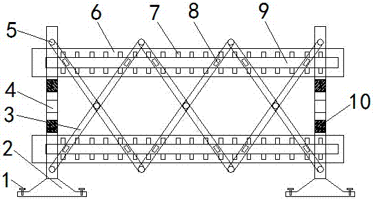
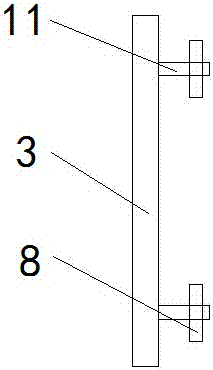
[0015] see Figure 1-2 , the present invention provides a technical solution: an electric safety fence, including a fixing screw 1, a base 2, a long rod 3, a vertical rod 4, a hinge 5, a horizontal plate 6, a slot 7, a buckle 8, a hollow slot 9, The warning bar 10 and the protruding rod 11, the long rods 3 are connected in pairs to form a grid, which can prevent the staff from entering the live area by mistake, ensure personal safety, effectively isolate the li...


PUM


Abstract

The invention discloses an electric safety fence. The electric safety fence comprises fixing screws, bases, long rods, vertical rods, hinges, transverse plates, clamping grooves, buckles, hollow slots, warning strips and protruding rods. The long rods intersect and are connected in pairs. The intersections and the two ends of every two long rods are connected through the hinges. The long rods are connected with the vertical rods through the hinges. The upper portions and the lower portions of the long rods are provided with the protruding rods. The buckles are arranged on the protruding rods. The upper portions and the lower portions of the vertical rods are connected with the transverse plates respectively. The bottoms of the vertical rods are connected with the bases. The fixing screws are arranged on the peripheries of the bases. The safety fence is reasonable in design and convenient to use; the length of the fence can be adjusted as required; the size of the fence can be reduced, the occupied space is reduced, and the safety fence is convenient to transport and quite practical.

Description

technical field [0001] The invention relates to the technical field of electric equipment, in particular to an electric safety fence. Background technique [0002] At present, the installation of safety fences is one of the important technical measures to ensure the safety of on-site workers. The safety fence can not only prevent staff from entering live areas by mistake and ensure personal safety, but also effectively isolate live equipment and ensure the normal operation of electrical equipment and power grids. However, for a long time, the traditional fences used to ensure the safety of substation construction operations have no practical, safe and effective means of layout, and the warning function is often greater than the actual protection effect. question. Chinese patent CN 204186139 U discloses a safety fence, including a fence unit. The fence unit includes two uprights and a cross telescopic fence connected between the two uprights. The cross telescopic fence is c...

Claims


Application Information

Patent Timeline
Patent Type & Authority Patents(China)
IPC IPC(8): E04H17/14E04H17/22
Inventor 褚景春袁凌潘磊董健李强王文亮林明张坤
Owner GUODIAN UNITED POWER TECH
Why Eureka
Try Eureka