centrifugal compressor

一种离心压缩机、阻力体的技术,应用在机械设备、发动机制造、发动机控制等方向,能够解决性能降低、复杂驱动机构、花费成本等问题,达到降低喘振极限流量的效果

Inactive Publication Date: 2019-08-23
MITSUBISHI HEAVY IND LTD
View PDF4 Cites 1 Cited by
  • Summary
  • Abstract
  • Description
  • Claims
  • Application Information

AI Technical Summary

Problems solved by technology

[0007] However, this requires a complex drive mechanism, which costs
In addition, there are problems such as reliability of the sliding part, performance degradation due to gaps in the sliding part, air leakage, etc.

Method used


Image

  • centrifugal compressor
  • centrifugal compressor
  • centrifugal compressor

Examples


no. 1 approach

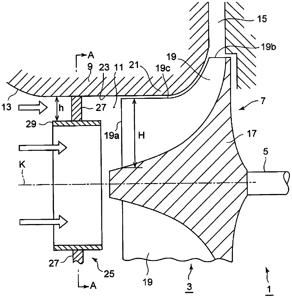
[0072] refer to Figure 1 ~ Figure 4B The first embodiment will be described.

[0073] The first embodiment is an embodiment in which the inner peripheral wall 23 of the intake passage 11 is provided with an inner peripheral resistance body 25 constituting a resistance body against the intake air flow.

[0074] The inner peripheral resistance body 25 is provided on the inner peripheral wall 23 between the air inlet 13 of the air inlet passage 11 and the vane 19, and is formed of an annular plate member 27. The outer peripheral end of the plate member 27 is attached to the inner peripheral wall 23 of the intake passage 11, and a cylindrical guide portion 29 extending in the axial direction of the intake passage 11 is attached to the inner peripheral end.

[0075] The center line of the guide part 29 coincides with the rotation axis k. By forming the guide part at the center part of the intake passage 11, the directivity of the intake air flow flowing in the center part of the ...

no. 2 approach

[0086] Next, refer to Figure 5 ~ Figure 7B A second embodiment will be described.

[0087] In the second embodiment, a central resistance body 41 is provided, and the central resistance body 41 is arranged at the central portion of the air intake passage 11 to form a resistance body to the intake air flow.

[0088] The central resistance body 41 is provided around the rotation axis k between the air inlet 13 of the air inlet passage 11 and the vane 19 and is formed of a disc-shaped plate member 43 .

[0089] A cylindrical guide portion 45 extending in the axial direction of the intake passage 11 is attached to cover the outer periphery of the plate member 43 . The outer peripheral portion of the guide portion 45 is attached to the inner peripheral wall 23 of the intake passage 11 via struts 47 provided at four locations along the peripheral direction.

[0090]In this way, the central resistance body 41 is provided inside the guide portion 45 , and the guide portion 45 can s...

no. 3 approach

[0099] Next, refer to Figure 8 A third embodiment will be described.

[0100] In the third embodiment, the plate member 43 of the second embodiment is made into a rotating valve body 51 .

[0101] Such as Figure 8 As shown, the disc-shaped central resistance body 53 is composed of an openable and closable valve body 51. The openable and closable valve body 51 takes the radial direction of the intake passage 11 as the central axis of rotation, and is fully open along the intake air flow. Rotate between closed and fully closed to block the intake air flow.

[0102] A valve body rotation shaft 55 is connected to the rotation center axis of the valve body 51, and the valve body rotation shaft 55 penetrates the guide portion 45. Furthermore, only one support 47 is made into an internal through structure, and the valve body rotation shaft 55 connects the support 47. Or, the valve body rotating shaft 55 is provided in its place instead of a support 47, and penetrates the compres...


PUM


Abstract

A centrifugal compressor, which is provided with a resistance body that radially narrows the channel section of the air intake channel connecting the rotating blades of the centrifugal compressor and the air inlet, so that the inflow speed of the blade towards the impeller can be increased, Reduce surge limit flow at low flow. The centrifugal compressor is characterized in that it has: a compressor casing (9) having an air inlet (13) and an air inlet passage (11) open to the direction of the rotating shaft; The impeller (7) that compresses the air that flows in from the port (13) is provided with a resistance body (27, 43) to the intake air flow on any part of the inner peripheral wall (23) side part or the center side part of the air intake passage (11). ), when the flow rate is low, by narrowing the cross-sectional area of ​​the air intake channel (11) by the resistance body (27, 43), the inflow velocity of the blade (19) towards the impeller is increased, and the intake air flow is directed towards the blade Hub side or shroud side bias flow of (19).

Description

technical field [0001] The present invention relates to a centrifugal compressor including an impeller rotated by a rotary shaft, and more particularly to a centrifugal compressor incorporated in an exhaust turbocharger. Background technique [0002] In engines used in automobiles, etc., in order to increase the output of the engine, there is known an exhaust turbocharger in which the turbine is rotated by the energy of the exhaust gas of the engine, and a centrifugal turbocharger directly connected to the turbine through a rotating shaft is used. The compressor compresses the intake air and supplies it to the engine. [0003] The centrifugal compressor used in this exhaust turbocharger is required to have a wide operating range, but when the flow rate decreases, the centrifugal compressor will experience an unstable phenomenon of surge, and when the flow rate increases, it will Choking occurs at the impeller or diffuser, so the flow range is limited. [0004] Therefore, i...

Claims


Application Information

Patent Timeline
Patent Type & Authority Patents(China)
IPC IPC(8): F04D29/44
CPCF04D29/00F04D29/668F04D17/10F04D27/0253F04D29/4213F04D29/441F04D29/464F05D2250/51F05D2270/64F05D2270/65F04D29/4206
Inventor 茨木诚一富田勋铃木浩
Owner MITSUBISHI HEAVY IND LTD
Why Eureka
Try Eureka