Al technical title is built by PatSnap Al team. It summarizes the technical point description of the patent document.
The technology of a corn threshing and material receiving device is applied in the field of agricultural machinery, which can solve the problems of difficulty, complexity, labor, and high labor intensity in corn threshing, and achieve the effects of simple structure, high threshing efficiency, and reduced labor intensity.
Inactive Publication Date: 2018-01-16
重庆潼双机械制造有限公司
View PDF7 Cites 0 Cited by
Summary
Abstract
Description
Claims
Application Information
AI Technical Summary
This helps you quickly interpret patents by identifying the three key elements:
Problems solved by technology
Method used
Benefits of technology
Problems solved by technology
[0002] Corn is one of the important sources of human food. It is loved by people for its extensive planting, considerable yield, rich nutrition and good taste. However, as everyone knows, picking corn is a very complicated and tiring work. Picking from the straw and transporting it out of the farmland, and then threshing can no longer get edible corn kernels. However, corn kernels are very difficult to thresh. In the past, they were manually threshed, with low work efficiency and high labor intensity. Blood bubbles and other problems
Method used
Image
Click on the blue label to locate the original text in one second.
Reading with bidirectional positioning of images and text.
Examples
Embodiment Construction
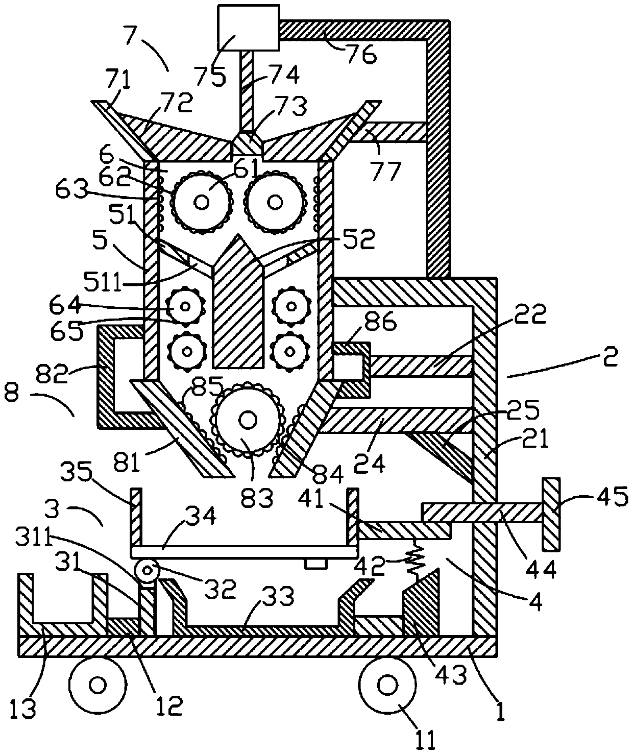
[0019] Such as figure 1 As shown, the device for corn threshing of the present invention includes a bottom plate 1, a support device 2 above the bottom plate 1, a receiving device 3 on the left side of the support device 2, and a receiving device 3 on the right side of the receiving device 3. The buckle device 4, the frame body 5 positioned above the receiving device 3, the first kneading device 6 positioned inside the frame body 5, the feeding device 7 positioned above the first kneading device 6 and the The second kneading device 8 below the frame body 5 .
[0020] Such as figure 1 As shown, the bottom plate 1 is in the shape of a cuboid, and the bottom plate 1 is placed horizontally. The bottom plate 1 is provided with a first receiving box 13 , a runner 11 at the bottom and a first fixed block 12 at the top. Described runner 11 is provided with two and is respectively positioned at the left and right sides, and described runner 11 is cylinder, and described runner 11 is ...
PUM
Abstract
The invention discloses a corn thresher. The corn thresher comprises a bottom plate, a support device, a collecting device, a fastening device, a frame, a first rubbing device, a feeding device and a second rubbing device. The bottom plate is provided with a first collecting box and a first fixing block; the support device comprises a first support, a first cross bar, a second cross bar and a first inclined bar; the collecting device comprises a first supporting rod, a first rotating shaft, a second collecting box, a first filter screen, a baffle ring and a vibrator; the fastening device comprises a first fastening rod, a first spring, a second fixing block, a second fastening rod and a gripping rod; a second inclined bar and a distributing block are provided inside the frame; the first rubbing device comprises a first roller, a first lug, a second lug, a second roller and a third lug; the feeding device comprises a feeding hopper, a centralizing block, a moving block, a pushing rod, a cylinder, a first fixing rack and a third cross bar; and the second rubbing device comprises a discharging hopper and a second fixing rack. The corn thresher provided by the invention can be used for threshing corn effectively, and is high in threshing efficiency.
Description
technical field [0001] The invention relates to the technical field of agricultural machinery, in particular to a device for threshing corn. Background technique [0002] Corn is one of the important sources of human food. It is loved by people for its extensive planting, considerable yield, rich nutrition and good taste. However, as everyone knows, picking corn is a very complicated and tiring work. Picking from the straw and transporting it out of the farmland, and then threshing can no longer get edible corn kernels. However, corn kernels are very difficult to thresh. In the past, they were manually threshed, with low work efficiency and high labor intensity. Problems such as blood bubbles occur. [0003] Therefore, it is necessary to provide a new technical solution to solve the above technical problems. Contents of the invention [0004] The object of the present invention is to provide a device for corn threshing that can effectively solve the above technical probl...
Claims
Application Information
Patent Timeline
Application Date:The date an application was filed.
Publication Date:The date a patent or application was officially published.
First Publication Date:The earliest publication date of a patent with the same application number.
Issue Date:Publication date of the patent grant document.
PCT Entry Date:The Entry date of PCT National Phase.
Estimated Expiry Date:The statutory expiry date of a patent right according to the Patent Law, and it is the longest term of protection that the patent right can achieve without the termination of the patent right due to other reasons(Term extension factor has been taken into account ).
Invalid Date:Actual expiry date is based on effective date or publication date of legal transaction data of invalid patent.