Improved locking ring metal

A technology of metal rings and frames, applied in printing, folders, etc., can solve the problem of scattered contents and achieve the effect of simplifying operations

Inactive Publication Date: 2016-03-02
U S RING BINDER CORP
View PDF16 Cites 2 Cited by
  • Summary
  • Abstract
  • Description
  • Claims
  • Application Information

AI Technical Summary

Problems solved by technology

[0007] use such as Figure 25 A conventional ferrule for a conventional trigger (such as Figure 24 The problem with the prior art metal rings shown in ) is that if they are dropped or otherwise mishandled, the metal rings can accidentally open and scatter the contents of the binder

Method used


Image

  • Improved locking ring metal
  • Improved locking ring metal
  • Improved locking ring metal

Examples


Embodiment Construction

[0043] The following detailed description illustrates the invention by way of example and not by way of limitation. This description clearly enables one skilled in the art to make and use the invention, and describes several embodiments, changes, variations, substitutions and uses of the invention, including what is presently believed to be the best mode of carrying out the invention. Furthermore, it should be understood that the invention is not limited in its application to the details of construction and the arrangement of parts set forth in the following description or shown in the drawings. The invention is capable of other embodiments and of being practiced or carried out in various ways. Also, it is to be understood that the phraseology and terminology used herein are for the purpose of description and should not be regarded as limiting.

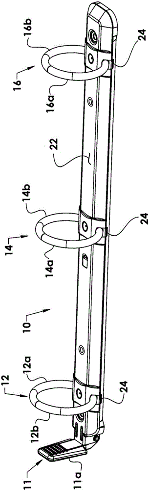
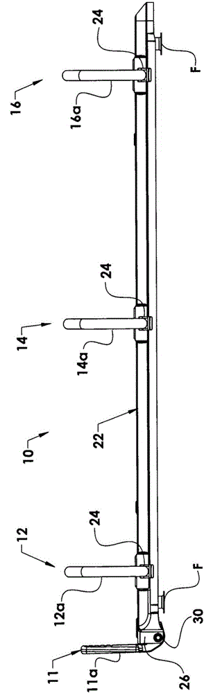
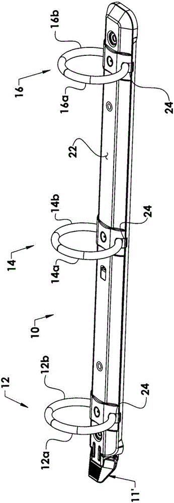
[0044] Referring to the accompanying drawings, the locking metal ring of the present invention for use in a binder ring (not shown)...


PUM


Abstract

A locking ring metal (10) includes binder rings (12, 14, 16) each formed by a pair of complementary shaped binder ring halves. Each ring half has an end attached a frame (18, 20). The frames are movable relative to each other to open and close the binder rings and are installed in a housing (22) at one end of which a trigger (11) is mounted. A travel bar (34) installed within the housing above the frames and not connected to the trigger includes blocking elements (50) which fit into respective brackets formed on the underside of the frames when the binder rings are closed to lock the binder rings in their closed position. A coil spring (48) attached to the travel bar and the housing biases the travel bar in the direction to open the binder rings.

Description

[0001] Cross References to Related Applications [0002] This application is a continuation-in-part of US Patent Application 13 / 827,559, filed March 14, 2013, which is based upon and claims the benefit of US Provisional Patent Application 61 / 727,944, filed November 19, 2012. [0003] Statement Regarding Government Sponsored Research or Development [0004] N / A technical field [0005] This invention relates to locking ferrules for use in binders; and more particularly, to an improved locking ferrule. Background technique [0006] As is well known in the art, the purpose of using ferrules in binders is to hold material, usually perforated paper or the like, so the material is easily accessible to the user and easily transported from one location to another. For this purpose, the metal ring has one or more loose-leaf rings, each loose-leaf ring comprising a pair of complementary shaped ring halves, wherein the outer ends of the ring halves are movable out of each other an...

Claims


Application Information

Patent Timeline
Patent Type & Authority Applications(China)
IPC IPC(8): B42F13/00
Inventor 保罗·惠利
Owner U S RING BINDER CORP
Why Eureka
Try Eureka