Al technical title is built by PatSnap Al team. It summarizes the technical point description of the patent document.
A multi-functional, fixture technology, applied in the direction of hand-held tools, manufacturing tools, manual tools for fasteners, etc., can solve the problems of tool loss, elastic tools that cannot meet the actual production requirements, and single function, so as to avoid loss Effect
Inactive Publication Date: 2016-03-23
SUZHOU CHUANGFENG PRECISION HARDWARE
View PDF7 Cites 2 Cited by
Summary
Abstract
Description
Claims
Application Information
AI Technical Summary
This helps you quickly interpret patents by identifying the three key elements:
Problems solved by technology
Method used
Benefits of technology
Problems solved by technology
In the prior art, wrenches are commonly used, such as dead wrenches, adjustable wrenches, etc., to fasten or loosen such parts. However, traditional elastic tools often cannot meet the actual production requirements, such as: dead wrench, usually a dead wrench can be used at most Fasteners of two sizes have a single function, and usually require multiple wrenches of various specifications to be used together. The number of tools is large, and the tools are easily lost or scattered during use.
Although the size range of the adjustable wrench is slightly wider, because the adjustment of the wrench lip is not flexible enough, and the adjustment range is limited, it is still necessary to frequently replace different tools when encountering devices with many types of fasteners, which cannot meet the actual production requirements. application
Method used
Image
Click on the blue label to locate the original text in one second.
Reading with bidirectional positioning of images and text.
Examples
Embodiment Construction
[0019] The present invention will be further described below in conjunction with the accompanying drawings. The following examples are only used to illustrate the technical solution of the present invention more clearly, but not to limit the protection scope of the present invention.
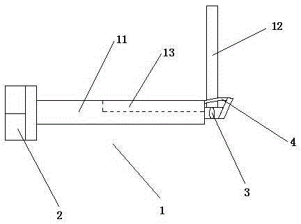
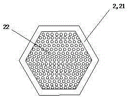
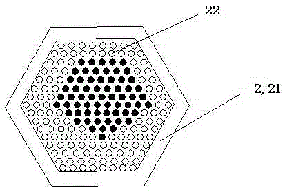
[0020] Such as Figure 1-3 As shown, a multi-functional disassembly jig includes a handle 1 and a head 2 located at one end of the handle 1. The head 2 includes a sleeve 21 and a rigid needle post 22 densely distributed inside the sleeve 21. The rigid needle post 22 The axis is parallel to the axis of the sleeve 21 , the rigid needle column 22 can elastically shrink along the axis of the sleeve 21 through the elastic element, and the length of the rigid needle column 22 does not exceed the length of the sleeve 21 .
[0021] Specifically, the above sleeve 21 is a hexagonal sleeve with a rough inner wall, and the outer peripheral surface of the rigid needle post 22 is a rough surface.
[0022] T...
PUM
Abstract
The invention discloses a multifunctional disassembling jig which comprises a handle and a head portion located at one end of the handle. The head portion comprises a barrel sleeve and rigid pin posts densely distributed in the barrel sleeve, and the axis of each rigid pin post is parallel to the axis of the barrel sleeve. The rigid pin posts can elastically contract inside the barrel sleeve in the axis direction of the barrel sleeve through elastic elements, and the length of each rigid pin post is not larger than the length of the barrel sleeve. The head portion of the disassembling jig can be suitable for various fasteners with more size ranges where the maximum diameter is not larger than the diameter of the barrel sleeve; in actual application, various types of disassembling jigs can be replaced by the multifunctional disassembling jig, so that the situation that jigs are lost since too many jigs are carried is avoided.
Description
technical field [0001] The invention relates to a multifunctional disassembly jig. Background technique [0002] Bolts, screws, nuts, studs, wire threaded sleeves, etc. are widely used mechanical parts for fastening and connection. They are widely used in various machinery, equipment, vehicles, ships, railways, bridges, buildings, structures, tools, instruments, Various fasteners can be seen on instruments and supplies. It is characterized by a wide range of varieties and specifications, different performances and uses, and the degree of standardization, serialization, and generalization is also extremely high. In the prior art, wrenches are commonly used, such as dead wrenches, adjustable wrenches, etc., to fasten or loosen such parts. However, traditional elastic tools often cannot meet the actual production requirements, such as: dead wrench, usually a dead wrench can be used at most Fasteners of two sizes have a single function, and usually require multiple wrenches of...
Claims
Application Information
Patent Timeline
Application Date:The date an application was filed.
Publication Date:The date a patent or application was officially published.
First Publication Date:The earliest publication date of a patent with the same application number.
Issue Date:Publication date of the patent grant document.
PCT Entry Date:The Entry date of PCT National Phase.
Estimated Expiry Date:The statutory expiry date of a patent right according to the Patent Law, and it is the longest term of protection that the patent right can achieve without the termination of the patent right due to other reasons(Term extension factor has been taken into account ).
Invalid Date:Actual expiry date is based on effective date or publication date of legal transaction data of invalid patent.