a limiting device

A technology of a limit device and a limit column, which is applied in the direction of applications, surgical instruments, trocars, etc., can solve problems such as insufficient advance travel, no sense of arrival, and failure to meet the needs of clinical operations, so as to improve accuracy and efficiency, and advance The effect of accurate position

Active Publication Date: 2018-04-03
SHANGHAI ORTHOPAIR MEDICAL CO LTD
View PDF6 Cites 0 Cited by
  • Summary
  • Abstract
  • Description
  • Claims
  • Application Information

AI Technical Summary

Problems solved by technology

[0002] Existing suturing devices do not have a dual or multi-linkage propulsion mechanism. After the needle passes through the tissue, it is pulled back to catch the front hair anchor, which is a one-time consumption. However, it is often necessary to pass through the soft tissue multiple times during the operation. Determine the optimal position, so the existing design does not meet the needs of actual clinical operations
[0003] When using thimble propulsion, the existing propulsion generally uses subjective feelings, and then uses printed scales to meet the needs of a certain amount of propulsion, which is imprecise, has no sense of arrival, needs to be observed at any time, and is inconvenient to use
[0004] The application number is: 201510543564.4, and the name is: a Chinese patent application for a soft tissue suturing device, which discloses a soft tissue suturing device. The application has the following defects: In this patent application, the process of advancing the soft elastic limit push part passes through the protrusion And the corresponding limit hole control, in the process of advancing, it is easy to advance due to uneven force transition or insufficient advancing stroke, and it needs to be advanced again, which affects the accuracy and efficiency of the operation

Method used


Image

  • a limiting device
  • a limiting device
  • a limiting device

Examples


Embodiment Construction

[0022] The preferred embodiments of the present invention are given below in conjunction with the accompanying drawings to describe the technical solution of the present invention in detail.

[0023] The limiting device provided by the present invention is installed on the medical soft tissue suturing device to limit the progress of the needle part of the medical soft tissue suturing device.

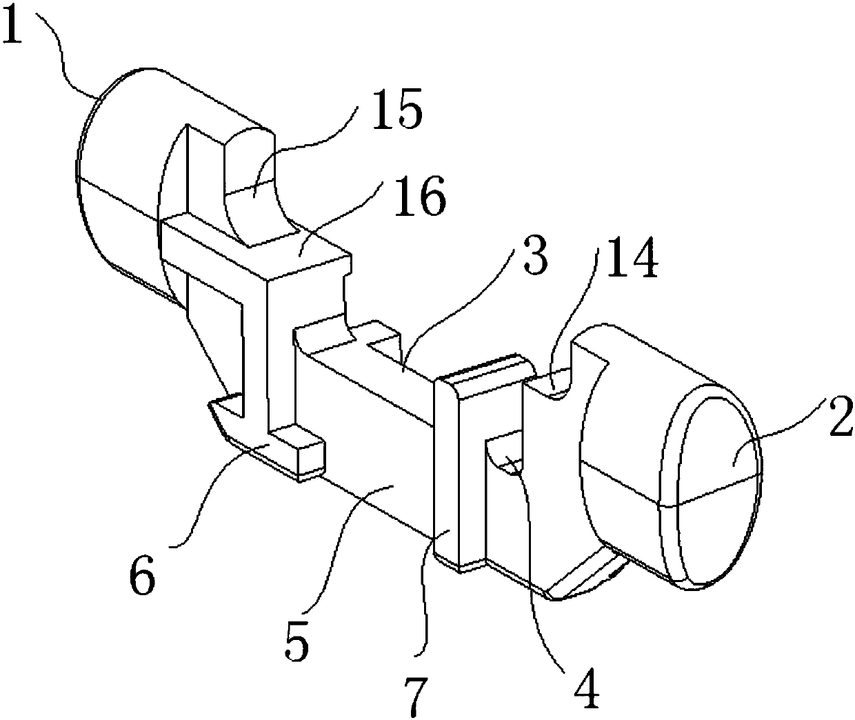
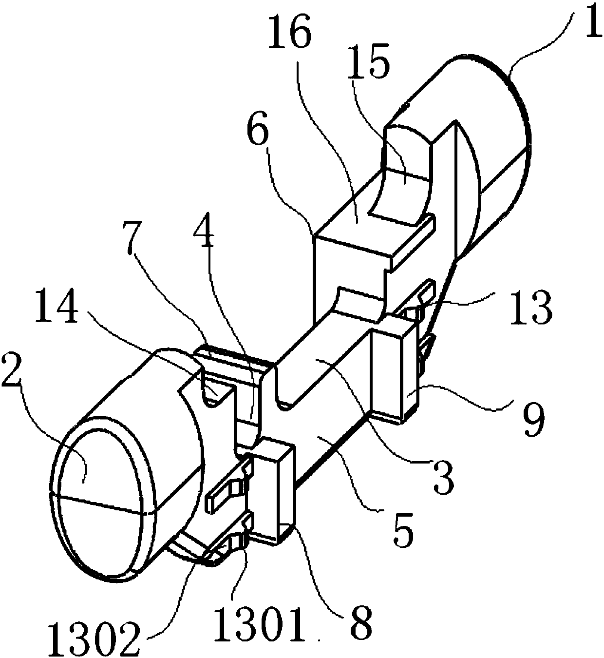
[0024] figure 1 It is one of the three-dimensional views of the overall structural schematic diagram of the present invention. figure 2 It is the second perspective view of the overall structure schematic diagram of the present invention. Such as Figure 1-2 As shown: the limiting device provided by the present invention includes pressing parts 1, 2 on both sides and a middle moving part 5, and a wide groove 3 and a narrow groove 4 are opened on the middle moving part 5; the present invention also includes two retaining posts 6, 7 and Two limit columns 8,9; two stop columns 6,7 and t...


PUM


Abstract

The invention relates to a limiting device. The limiting device is arranged on a medical soft tissue suturing device and is used for limiting a propulsion progress of a needle part of the medical soft tissue suturing device. The limiting device comprises pressing parts arranged at the two sides and a middle moving part, wherein a wide slot and a narrow slot are formed in the middle moving part; the limiting device is arranged on the lower shell of the medical soft tissue suturing device, and sliding grooves matched with the wide slot and the narrow slot in the upper shell of the medical soft tissue suturing device slide in the wide slot and the narrow slot or are blocked on a '1'-shaped blocking column by pressing the pressing parts arranged at the two sides and moving the middle moving part, so as to realize propulsion or stop of the needle part of the medical soft tissue suturing device. The limiting device provided by the invention can overcome the defects that excessive propulsion or insufficient propulsion stroke can be easily caused by a nonuniform force, propulsion needs to be carried out again and operation accuracy and efficiency are influenced when the propulsion progress of a propulsion part is controlled by virtue of bulges and corresponding limiting holes.

Description

technical field [0001] The invention relates to a limiting device, in particular to a limiting device for making the pushing position of the whole medical soft tissue suturing device more accurate. Background technique [0002] Existing suturing devices do not have a dual or multi-linkage propulsion mechanism. After the needle passes through the tissue, it is pulled back to catch the front hair anchor, which is a one-time consumption. However, it is often necessary to pass through the soft tissue multiple times during the operation. Determine the optimal position, so the existing design does not meet the needs of actual clinical operations. [0003] When the thimble is used for propulsion, the existing propulsion generally uses subjective feelings, and then uses printed scales to meet the needs of a fixed amount of propulsion, which is imprecise, has no sense of arrival, needs to be observed at any time, and is inconvenient to use. [0004] The application number is: 201510...

Claims


Application Information

Patent Timeline
Patent Type & Authority Patents(China)
IPC IPC(8): A61B17/04A61B17/06
CPCA61B17/0482A61B17/0491A61B17/06066A61B2017/0464
Inventor 王少白
Owner SHANGHAI ORTHOPAIR MEDICAL CO LTD
Why Eureka
Try Eureka