Fitting of an at least liftable, but preferably also displaceable wing of windows or doors

A technology of wing fan and accessories, applied in the field of locking devices, can solve the problems of visual damage danger, failure to realize automatic descending device, consumption, etc., and achieve the effect of removing pollutants and improving service life

Active Publication Date: 2016-05-25
SIEGENIA FRANK
View PDF5 Cites 0 Cited by
  • Summary
  • Abstract
  • Description
  • Claims
  • Application Information

AI Technical Summary

Problems solved by technology

[0008] Since the known fittings only concern sliding and non-lifting flaps with subsequent movement of the window or door, an automatic lowering device is not realized
Furthermore, the locking device proves to be complex and thus also cost-intensive in production
Furthermore, the lo...

Method used


Image

  • Fitting of an at least liftable, but preferably also displaceable wing of windows or doors
  • Fitting of an at least liftable, but preferably also displaceable wing of windows or doors
  • Fitting of an at least liftable, but preferably also displaceable wing of windows or doors

Examples


Embodiment Construction

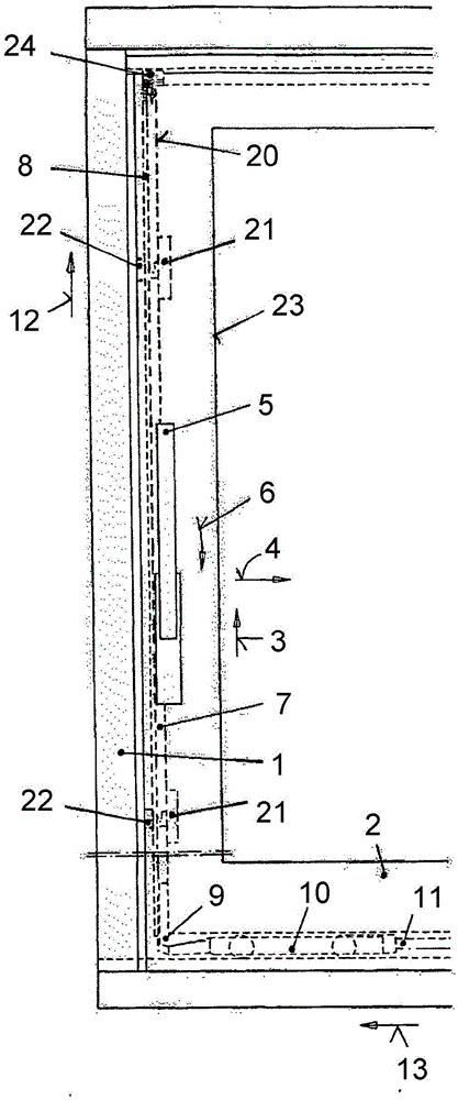
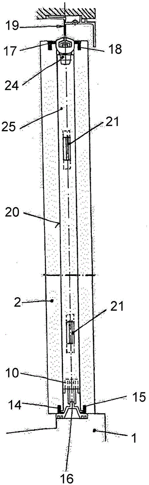
[0037] In the fixed frame 1 , the leaf 2 can be lifted according to the arrow 3 and can then be moved in the direction of the arrow 4 , wherein the arrow 4 symbolizes the opening direction. The lifting takes place in a known manner by means of an operating handle 5 designed as a handle, which is pivoted for this purpose according to the arrow 6 of the rotational movement. This rotational movement is transmitted to the connecting rod 8 via the actuating lever 7 of known design, which is arranged in the fitting groove 20 . The fastening tie rod 7 is likewise coupled in a known manner to the front carriage 10 via the lower corner deflection 9 . The connecting rod 11 leads to a second, rear carriage, not shown. Attached figure 1 Shown is a window or door comprising a fixed frame 1 and a non-illustrated leaf or fixed door frame mounted in a fixed position. Furthermore, the window or door is equipped with a movable leaf 2 . By the rotary movement 6 of the actuation handle 5 , th...


PUM


Abstract

The invention relates to a fitting of a wing (2) of a window or a door that can at least be lifted and/or tilted, but preferably can also be displaced, having a guide rail (16), wherein on the vertical wing spar (23) inside a fitting groove (20) of the wing (2), an actuating rod assembly (7) is located, which has a drive rod (8), which by means of an actuation member (5) can be displaced upwardly, for lowering the wing (2), and which by way of a corner deflection (9) transfers the displacement to at least one coupled slide mechanism (10). The fitting has a locking device (21), which by means of a housing (26) is fastened to the actuating rod assembly (7) inside the fitting groove (20), and which can be coupled to the actuating rod assembly (7) by way of a guide part (24). The guide part (24) can be moved by actuating the drive rod (8) of the actuating rod assembly (7), and transfers a pivot latch (29), which is controlled on the guide part (24) by means of an actuator guide (27), and which is rotatably mounted on the housing (26) of the locking device (21) via a pivot point (28), from an opening position located in a concealed manner in the housing (26) inside the actuating rod assembly (7) against the direction for lowering the wing (2) into a free operating field (30) of a locked position. The pivot latch (29) has a first connecting link (31), which during the transition into the locked position is in form-fit engagement with a peg (32) mounted to the outer frame (1) and arranged on the locking engagement (22). The pivot latch (29) has a second connecting link (33), which, extending nearly in parallel with the first connecting link (31) and arranged at the end (34) that is more distant from the point of rotation (28), in engagement with the peg (32), forms a gap opening position.

Description

technical field [0001] The invention relates to an attachment of at least a liftable, but preferably also movable, leaf of a window or door according to the preamble of claim 1 . In this context, the invention relates in particular to a locking device with an actuating lever arranged on the leaf, said actuating lever having a linkage, which is displaceable downwards by means of an actuating handle in order to lower the leaf. Background technique [0002] This lowering, due to the own weight of the leaf, thus brings about a hermetic locking of the leaf relative to the frame. [0003] Usually liftable wings are additionally adjusted, in particular moved sideways, after lifting. Thus, eg in the case of a door, the leaves release the access opening. In the closed position, the leaf must be as tight as possible relative to the fixed frame. For this purpose, the leaves are equipped with sealing strips or the like, which bear against corresponding counter-sealing surfaces of the...

Claims


Application Information

Patent Timeline
IPC IPC(8): E05B65/08E05D15/56
CPCE05B65/0811E05C9/1808E05C9/1875E05C17/60E05D15/565E05Y2800/12E05Y2900/148E05B65/0835E05C3/006E05C3/047E05D13/00E05D15/0621E05Y2201/684
Inventor W·贝伦斯T·比尔布劳尔S·施赖纳
Owner SIEGENIA FRANK
Why Eureka
Try Eureka