Fingerprint identification module, fingerprint identification device and display device

A fingerprint identification module and fingerprint identification technology, which is applied in the directions of acquiring/arranging fingerprints/palmprints, character and pattern recognition, and printing image collection, etc., which can solve the problem of reducing the proportion of display devices in the fingerprint identification area, affecting user experience, and processing difficulty and cost increases

Active Publication Date: 2016-08-10
BOE TECH GRP CO LTD
View PDF6 Cites 47 Cited by
  • Summary
  • Abstract
  • Description
  • Claims
  • Application Information

AI Technical Summary

Problems solved by technology

[0003] At present, the fingerprint recognition function can generally only be realized in the non-display area of ​​the display device, but the fingerprint recognition function cannot be realized in the display area, which leads to a significant reduction in the proportion of the fingerprint recognition area in the entire display device, thus affecting the user experience.
[0004] On this basis, if the capacitive fingerprint recognition module is to be integrated in the display area of ​​the display device, not only the capacitive f

Method used


Image

  • Fingerprint identification module, fingerprint identification device and display device
  • Fingerprint identification module, fingerprint identification device and display device
  • Fingerprint identification module, fingerprint identification device and display device

Examples


Embodiment Construction

[0041] The following will clearly and completely describe the technical solutions in the embodiments of the present invention with reference to the accompanying drawings in the embodiments of the present invention. Obviously, the described embodiments are only some, not all, embodiments of the present invention. Based on the embodiments of the present invention, all other embodiments obtained by persons of ordinary skill in the art without making creative efforts belong to the protection scope of the present invention.

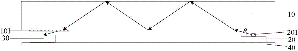
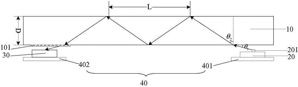
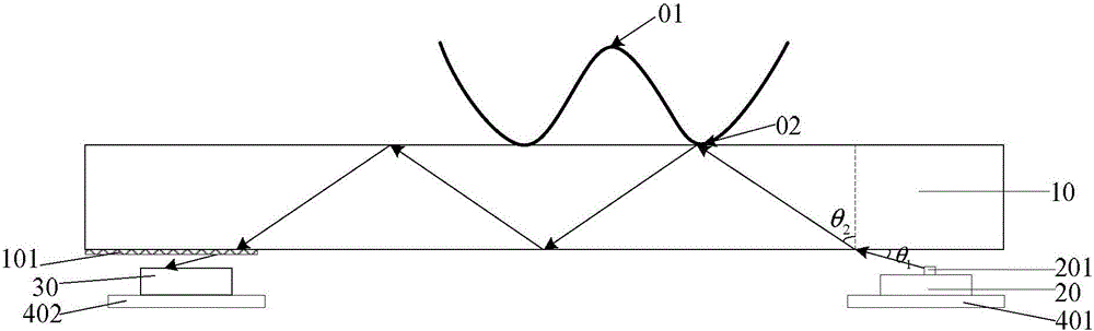
[0042] An embodiment of the present invention provides a fingerprint recognition module, as shown in FIG. 1 and FIG. 2 , including: a transparent substrate 10 , a transmitting part 20 , a receiving part 30 and a moving part 40 . The transmitting part 20 and the receiving part 30 are disposed close to opposite sides of the transparent substrate 10 respectively, and the transmitting part 20 and the receiving part 30 are fixed on the moving part 40 .

[0043] The...


PUM


Abstract

The invention discloses a fingerprint identification module, a fingerprint identification device and a display device, relating to the fingerprint recognition technology field. A fingerprint recognition function can be realized in a display area of a display device. The fingerprint identification module, the fingerprint identification device and the display device improve the user experience and are low in cost and easy to realize. The fingerprint identification module comprises a transparent substrate, an emission part, a reception part and a moving part; the emission part and the reception part are positioned in proximity to two opposite sides of a transparent substrate; the emission part and the reception part are fixed on the moving part; the emission part comprises a plurality of light sources which are arranged side by side; the light emitted by the light source goes into the transparent substrate with a first angle Theta 1 and is transmitted in the transparent substrate in a mode of full reflection; the transparent substrate is provided with a regulation structure in order to allow the light which is transmitted in the transparent substrate in a full reflection mode to exit and then the light is transmitted to the reception part; the reception part is used for receiving the light of the light source which enters the transparent substrate and exists through a regulation structure; and the moving part is used for enabling the emission part and the reception part to move simultaneously in the same direction for same displacements. The fingerprint identification module, the fingerprint identification device and the display device are used for finger identification.

Description

technical field [0001] The invention relates to the technical field of fingerprint identification, in particular to a fingerprint identification module, a fingerprint identification device and a display device. Background technique [0002] With the continuous improvement of living standards, various terminal devices have become necessities in life, and users have higher and higher requirements for terminal devices. Among them, since fingerprint recognition has an excellent privacy protection function, it is widely installed in various terminal devices to increase user experience and security. [0003] At present, the fingerprint identification function can generally only be implemented in the non-display area of ​​the display device, but the fingerprint identification function cannot be implemented in the display area, which leads to a significant reduction in the proportion of the fingerprint identification area to the entire display device, thereby affecting user experien...

Claims


Application Information

Patent Timeline
IPC IPC(8): G06K9/00G06V10/141
CPCG06V40/1324G06V40/1318G06V10/141
Inventor 邹祥祥
Owner BOE TECH GRP CO LTD
Why Eureka
Try Eureka