Backlight module, plat panel display and design method of positioning element of flat panel display

A technology for backlight modules and positioning components, which is applied to optical components, light source fixing, instruments, etc., can solve the problem of uneven brightness in the visible area, and achieve the effect of improving quality

Inactive Publication Date: 2010-04-21
AU OPTRONICS CORP
View PDF0 Cites 3 Cited by
  • Summary
  • Abstract
  • Description
  • Claims
  • Application Information

AI Technical Summary

Problems solved by technology

[0005] The invention provides a design method of a backlight module, a flat panel display and its positioning components to overcome the defect of uneven luminance in the visible area of ​​the prior art

Method used


Image

  • Backlight module, plat panel display and design method of positioning element of flat panel display
  • Backlight module, plat panel display and design method of positioning element of flat panel display
  • Backlight module, plat panel display and design method of positioning element of flat panel display

Examples


Embodiment Construction

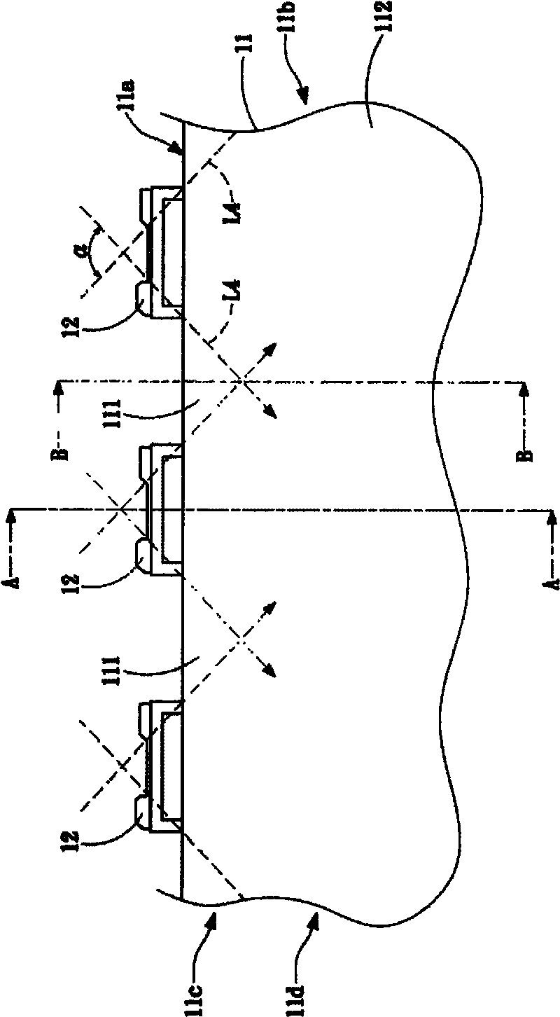
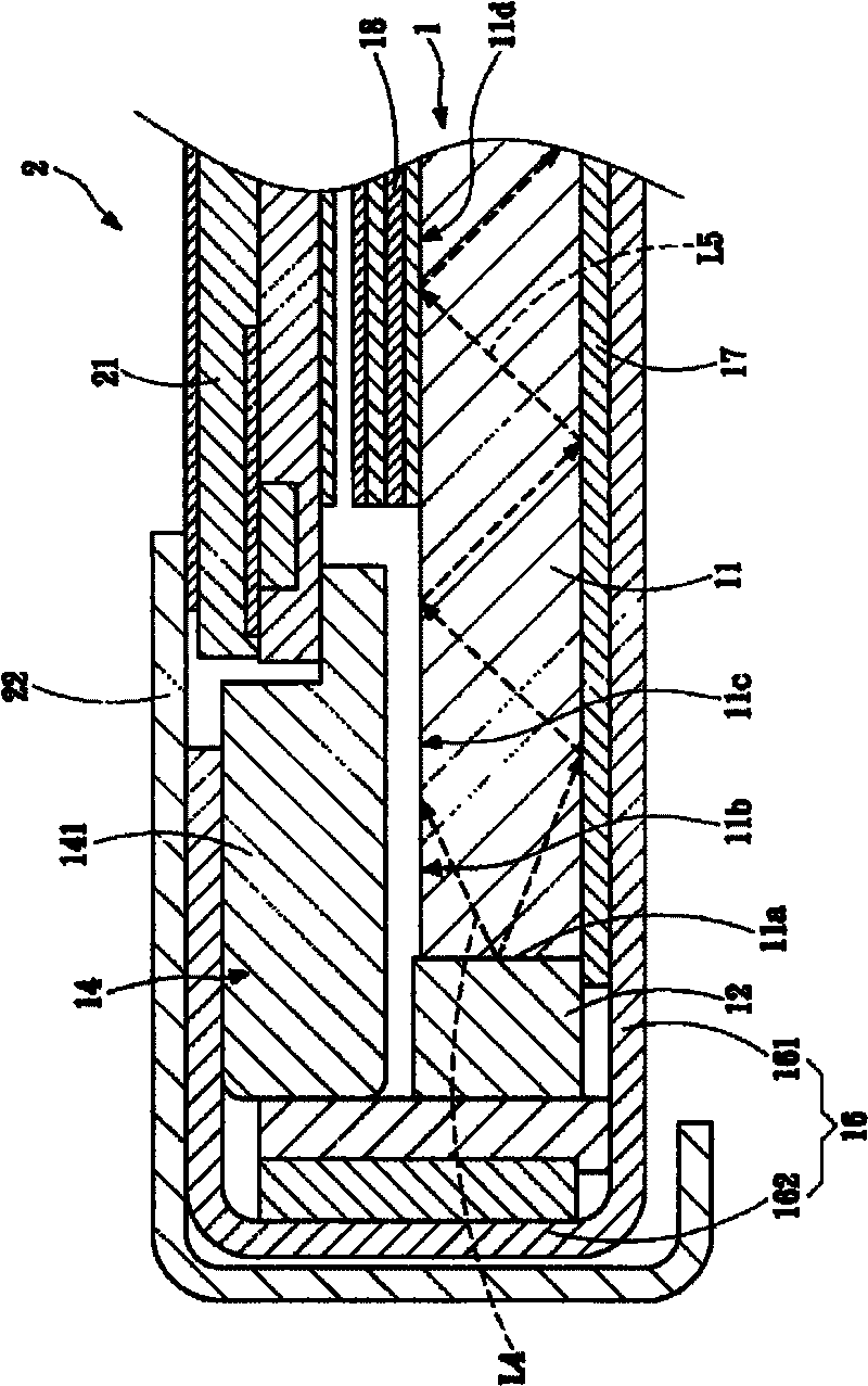
[0038] figure 2 and Figure 3A , Figure 3B and Figure 4A A first embodiment of the present invention is shown. The backlight module 1 includes: a light guide plate 11 , a plurality of light emitting elements 12 , and a positioning element 14 . Figure 3A for figure 2 The A-A section diagram, Figure 3B for figure 2 The B-B section diagram, Figure 4A Then it is a schematic diagram of the optical performance of this embodiment. Wherein, for the convenience of description and performance of the technical features of the present application, figure 2 Only the light guide plate 11 and the light emitting element 12 are kept, while other elements are omitted.

[0039] The light guide plate 11 is roughly in the shape of a parallelogram, including a light-incident surface 11 a and an upper surface 11 b , wherein the upper surface 11 b intersects the light-incident surface 11 a.

[0040] A plurality of light-emitting elements 12, each light-emitting element 12 preferabl...


PUM

PropertyMeasurementUnit
refractive indexaaaaaaaaaa

Abstract

The invention discloses a backlight module which comprises a light guide plate, a plurality of light emitting elements and a positioning element. The light guide plate comprises a light incoming side and an upper surface which intersects at the light incoming side; the light emitting elements have light emitting angles and are arranged in the range of the light emitting angles and respectively project light to the light incoming side, and the light forms a plurality of dark zones at the position of the light guide plate beyond the range of the light emitting angles; and the positioning element comprises a plurality of protruding parts which protrude to the upper surface and respectively support against the dark zones. The invention also discloses a flat panel display and a design method of a positioning element of the same.

Description

technical field [0001] The invention relates to a backlight module, in particular to a design method of a backlight module capable of improving luminance uniformity, a flat panel display and a positioning component thereof. Background technique [0002] With the rapid progress and evolution of display technology, the traditional cathode ray tube (cathode ray tube, CRT) has been gradually eliminated due to problems such as poor space utilization and large energy consumption, and has been replaced by light, thin, short, small LCD (liquid crystal display, LCD). Due to the advantages of high display quality, low energy consumption and no radiation, liquid crystal displays are widely used in notebook computers, computer screens, mobile phones, personal digital assistants (PDAs), digital cameras, digital Among communication, information or consumer electronics products such as cameras and LCD TVs. [0003] Liquid crystal displays mainly use liquid crystal panels for display. Sin...

Claims


Application Information

Patent Timeline
Patent Type & Authority Applications(China)
IPC IPC(8): F21S8/00F21V8/00F21V17/00G02F1/13357G02F1/1333F21Y101/02
Inventor 邱继锋王景辉简叶恩
Owner AU OPTRONICS CORP
Why Eureka
Try Eureka