Structures and Methods for the Joint Delivery of Fluids and Light

a technology of fluids and joints, applied in the direction of catheters, spectroscopy diagnostics, therapy, etc., can solve the problems of low optical absorption, low optical absorption, and high optical intensities local to optical fiber endfaces, etc., to facilitate interaction, low optical absorption, and low optical absorption

Inactive Publication Date: 2005-12-22
DEUT HARVEY +1
View PDF13 Cites 211 Cited by
  • Summary
  • Abstract
  • Description
  • Claims
  • Application Information

AI Technical Summary

Benefits of technology

[0005] This invention satisfies the requirement to guide light and fluids simultaneously by providing tubing with an annular core surrounded by a low index cladding comprised of the inner and outer surfaces of the tube. This invention describes the design of tubing which acts as a waveguide itself, eliminating the need for optical fiber(s). This is achieved by designing and fabricating rigid or flexible tubing which consists of a hollow cylindrical core of low optical absorption and scatter, surrounded by inner and outer cylindrical claddings of lower index of refraction. The one or more inner chambers can simultaneously deliver fluids without impacting the optical characteristics of the waveguide. In those applications in which properties of the fluid are to be sensed, cladding regions can be selectively removed to facilitate interaction between the fluid and light guides in a highly controllable fashion. This results in several practical advantages. First, it eliminates the need to embed or attach optical fiber to the tubing. Second, the cross section of the tubing core is relatively large in size (approximately 0.5-3 mm thick wall) and NA (about 0.5) compared to a single mode or multimode fiber core (0.01 to 0.05 mm in diameter) with NA's of between 0.12 to 0.5. As a result, the alignment, source beam divergence and spatial coherence requirements to efficiently couple light into the waveguide are relaxed by the use of the tube waveguides disclosed herein. A halogen, incandescent or fluorescent light bulb, chemiluminescent or LED light source may suffice instead of a more costly laser source.
[0006] This waveguide structure further offers flexibility in tailoring the spectral characteristics of the illumination to cover a broad spectral range (10's to 100's of nm, for example) of potential importance for spectroscopy. In some situations it is advantageous that the light source include ultraviolet wavelengths for use in locally preventing infection, for example, while at the same time using near infrared wavelengths to locate the end of the device deep within tissue. Light from single or multiple sources of different wavelengths can be efficiently coupled into the tube waveguide because of the large cross section. This use of structured illumination potentially delivered to different spatial locations along the tube allows additional functionality to be realized. In addition, the local removal of the tubing cladding can be used to optically detect the presence of fluids within the waveguide; for example, the light guidance can be compromised if the liquid index of refraction is higher than that of the tubing core. Finally, the high optical intensities local to an optical fiber endface also have the potential to damage tissue, an effect which is reduced by using a large core tube waveguide.

Problems solved by technology

In addition, the local removal of the tubing cladding can be used to optically detect the presence of fluids within the waveguide; for example, the light guidance can be compromised if the liquid index of refraction is higher than that of the tubing core.
Finally, the high optical intensities local to an optical fiber endface also have the potential to damage tissue, an effect which is reduced by using a large core tube waveguide.
While fiberoptic light wands have been proposed for this purpose, clinical studies have cast doubt on the effectiveness of these techniques because of the increased procedural complexity.

Method used


Image

  • Structures and Methods for the Joint Delivery of Fluids and Light
  • Structures and Methods for the Joint Delivery of Fluids and Light
  • Structures and Methods for the Joint Delivery of Fluids and Light

Examples


example

IR Light Guided Catheter

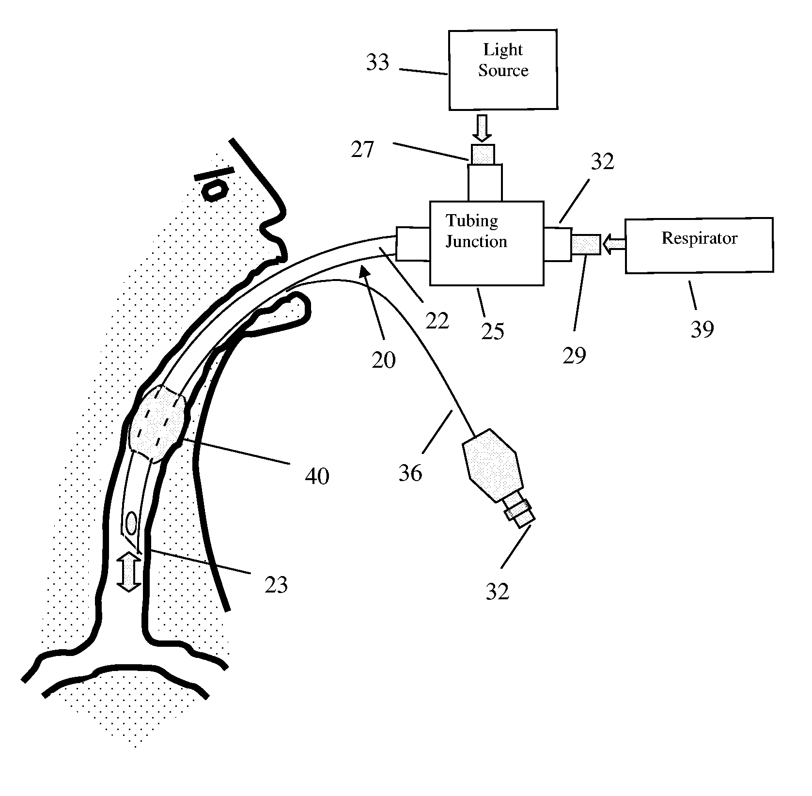
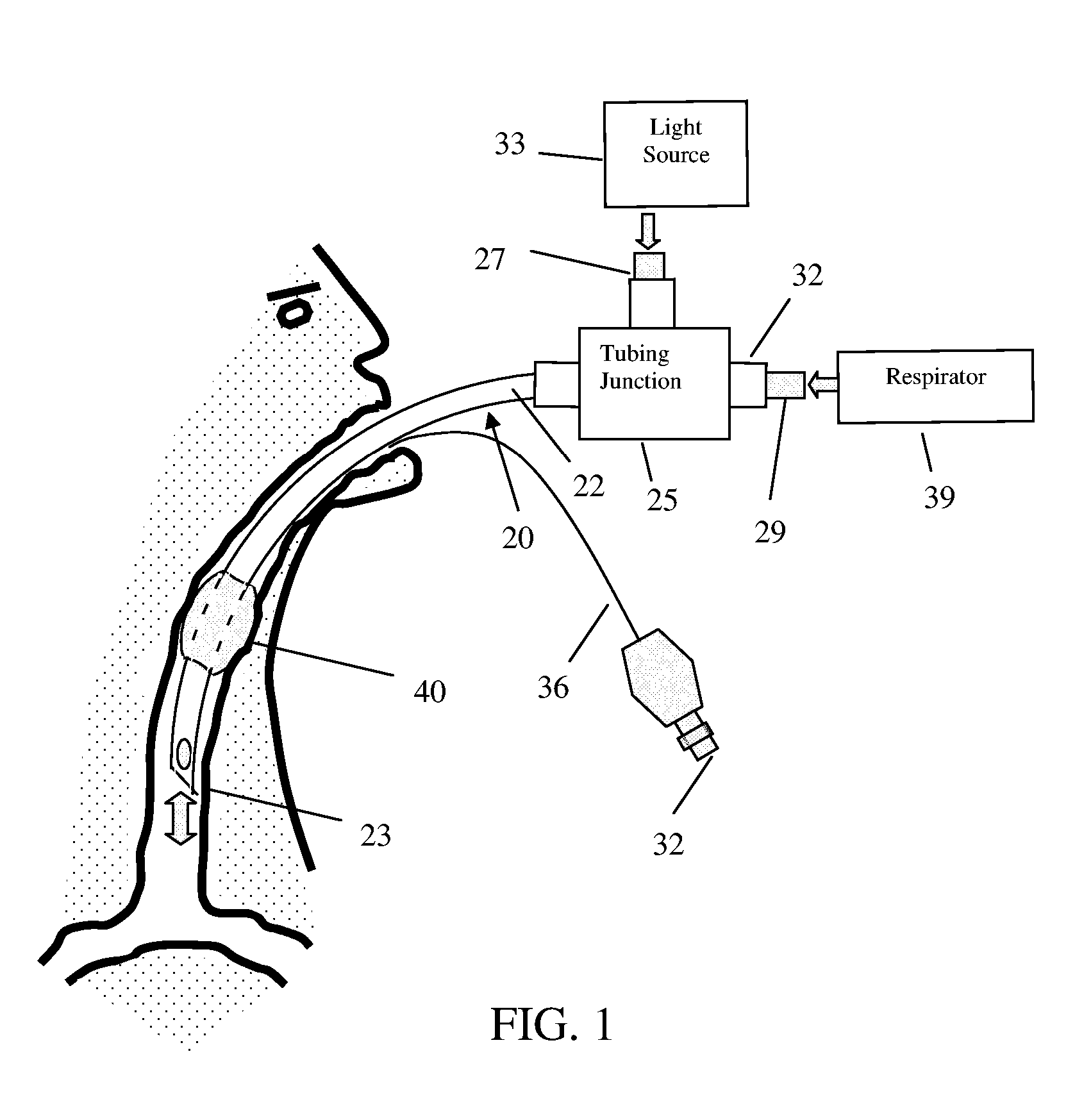
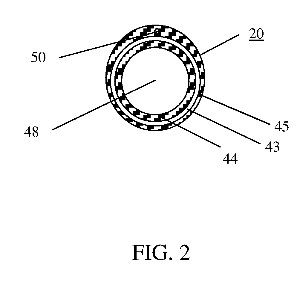
[0061] A nurse or doctor have no direct feedback regarding the location of the catheter tip when inserting a tube-like catheter into a vein or artery in the absence of a relatively expensive fluoroscopy procedure. This leads to a higher incidence of errors in the placement of the catheter and possible serious medical complications. Bard Inc. had introduced a CathTrack™ catheter locating system based on electronic detection which was not commercially successful because the limited spatial resolution and inconvenience of usage. Alternately, fluoroscopy or ultrasound imaging techniques may provide a real time image of the catheter location; however, these systems are cost prohibitive in most situations. Today, a post implantation x-ray is performed after catheter insertion to confirm catheter tip location and to ensure that the catheter is not being pinched by the clavicle or ribs. This provides a location accuracy of about + / −1 cm. Approaches using near infrar...


PUM


Abstract

Guides for intubation which simultaneously transport fluids and light into a body site are tube-like in structure and consist of a hollow cylindrical optical core surrounded on its inner and outer walls by a cladding of lower index of refraction. Materials comprising the optical core are selected such that the optical absorption and scatter are sufficiently small to transport light efficiently over an extended distance as fluid is transferred through the tube interior. Methods of fabrication, light coupling and light delivery using waveguide tubes are disclosed. Particular applications of waveguide tubes in the medical and industrial sectors are described.

Description

REFERENCE TO RELATED APPLICATIONS [0001] This application relies for priority on provisional application 60 / 581,401 filed on Jun. 21, 2004 and entitled “Structures and Methods for the Joint Delivery of Fluids and Light,” and on provisional application 60 / 588,573 filed on Jul. 16, 2004 and entitled “Integrated Light and Fluid Waveguides.”BACKGROUND OF THE INVENTION [0002] Structures which transmit fluids (i.e., liquids and gases) or light, but not both, are widely available in many different forms. For instance, medical devices such as catheters, cannulas and endoscopes are constructed of various types of tubing to facilitate the transport or exchange of fluids during medical procedures. The effectiveness of these procedures may be considerably enhanced by developing a straightforward method of delivering illumination through these devices, while retaining their small form factor. Presently, the transport of fluids is effectively achieved by the tubular structure, but the simultaneou...

Claims


Application Information

Patent Timeline
Patent Type & Authority Applications(United States)
IPC IPC(8): A61B1/267A61B5/00A61M15/00A61M16/04A61N5/06
CPCA61B1/07A61B1/267A61B5/0075A61B5/0084A61M16/0434A61M16/0463A61B1/015A61N2005/0604A61N2005/0651A61M16/0422A61B1/00154A61B1/0017A61N5/0601
Inventor DEUTSCH, HARVEYKEWITSCH, ANTHONY
Owner DEUT HARVEY
Why Eureka
Try Eureka