Optical imaging device

a technology of optical imaging and optical tubes, applied in the field of optical imaging devices, can solve the problems of difficult to identify whether the light is fluorescence, interfere with smooth observation, and become difficult to detect only fluorescence coming from the subject, so as to reduce unnecessary lights

Active Publication Date: 2007-03-01
OLYMPUS CORP
View PDF9 Cites 209 Cited by
  • Summary
  • Abstract
  • Description
  • Claims
  • Application Information

AI Technical Summary

Benefits of technology

[0018] It is an object of the present invention to provide an optical imaging device that can be used for both fluorescence o

Problems solved by technology

Particularly, in the case when the positional relationship of the illumination light, subject and light receiving optical system is the positional relationship where the portions satisfy regular reflection conditions, the above mentioned fluorescence and Raman scattering lights from the illumination light path generate brighter images, which makes it difficult to identify whether the light is from fluorescence which comes from the subject or fluorescence or Raman scattering lights which comes from the illumination light path, and interferes with smooth observation.
Therefore in a conventional endoscope apparatus, it may become difficult to detect only fluorescence which comes from the subject if the reflected light of the fluorescence and Raman scattering lights mix in.
The Raman scattering lights measurement device acc

Method used


Image

  • Optical imaging device
  • Optical imaging device
  • Optical imaging device

Examples


embodiment 1

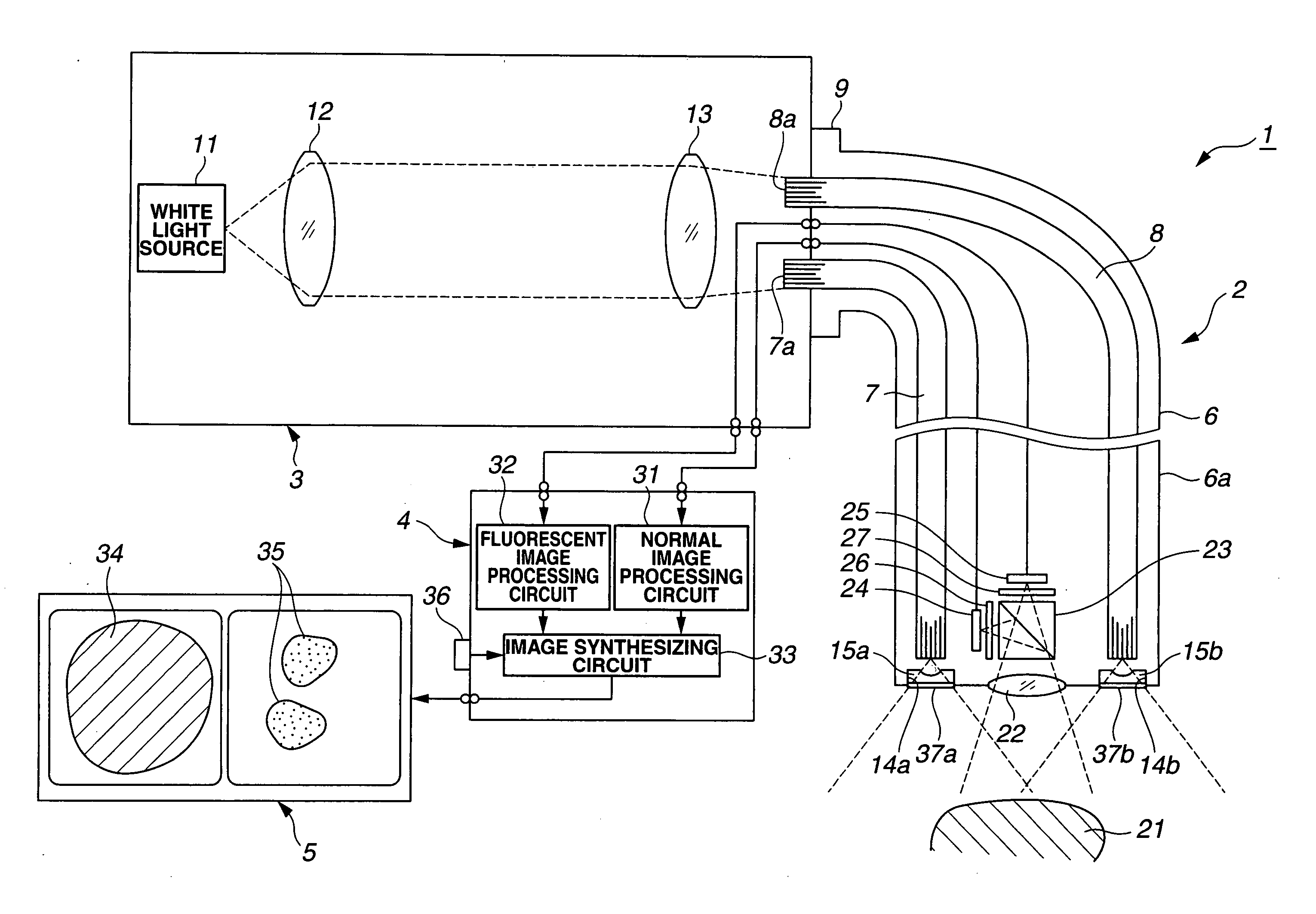
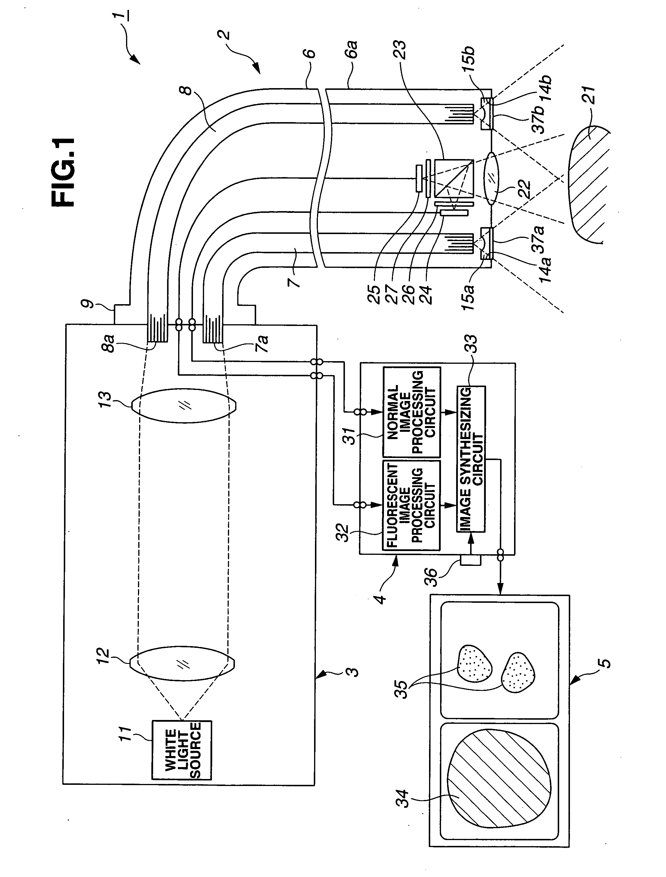
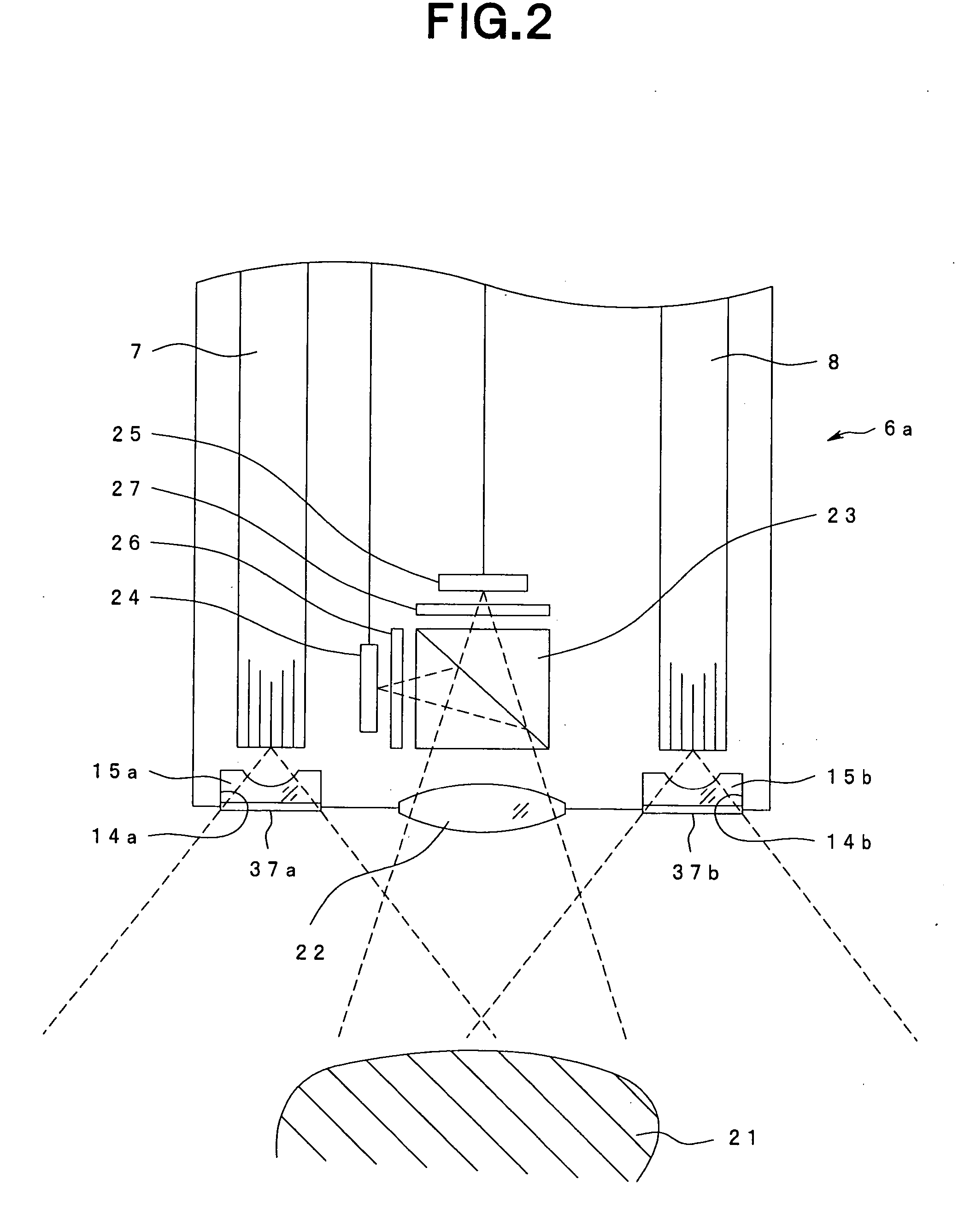
[0097]FIG. 1 to FIG. 10 are related to Embodiment 1 of the present invention, where FIG. 1 is a diagram depicting an entire configuration of the optical imaging device according to Embodiment 1, FIG. 2 is an enlarged view depicting a key section at the distal portion of the insertion section of the endoscope shown in FIG. 1, FIG. 3 is a graph depicting the wavelength characteristic of the lights which are transmitted through the light guide in FIG. 2 and entered the illumination lens, FIG. 4 is a graph depicting the filter characteristic of the illumination light filter in FIG. 2, FIG. 5 is a graph depicting the wavelength characteristic of the lights which are transmitted through the illumination light filter in FIG. 2 and irradiated onto the subject, FIG. 6 is a graph depicting the wavelength characteristic of the return light from the subject in FIG. 2, FIG. 7 is a graph depicting the filter characteristic of the excitation light cut filter in FIG. 2, FIG. 8 is a graph depicting ...

embodiment 2

[0134]FIG. 11 to FIG. 12 are related to Embodiment 2 of the present invention, where FIG. 11 is a diagram depicting an entire configuration of the optical imaging device according to Embodiment 2, and FIG. 12 is a graph depicting the wavelength characteristic of the optical imaging device in FIG. 11. The above Embodiment 1 has a configuration where the present invention is applied to the optical imaging device which performs infrared fluorescence observation by detecting the fluorescence in the near infrared band, but Embodiment 2 has a configuration where the present invention is applied to an optical imaging device which performs visible light fluorescence observation by detecting the fluorescence in the visible light band. The rest of the configuration is the same as Embodiment 1, therefore description thereof is omitted, and the same components are described denoting with the same reference symbols.

[0135] As FIG. 11 shows, the optical imaging device 1B of Embodiment 2 is config...

embodiment 3

[0165]FIG. 13 to FIG. 26 are related to Embodiment 3 of the present invention, where FIG. 13 is a diagram depicting an entire configuration of the optical imaging device according to Embodiment 3, FIG. 14 is a graph depicting the filter characteristic of the excitation light filter in FIG. 13, FIG. 15 is a graph depicting the wavelength characteristic of the light which is transmitted through excitation light filter in FIG. 13, FIG. 16 is a graph depicting the filter characteristic of the RGB filter in FIG. 13, FIG. 17 is a graph depicting the wavelength characteristic of the light which is transmitted through the light guide in FIG. 13 and is incident on the illumination optical system, FIG. 18 is a graph depicting the filter characteristic of the illumination light filter in FIG. 13, FIG. 19 is a graph depicting the wavelength characteristic of the light which is transmitted through the illumination light filter in FIG. 13, FIG. 20 is a graph depicting the filter characteristic of...


PUM


Abstract

An optical imaging device of the present invention comprises: a light source device; a light guide and illumination lens, provided in an insertion section that can be inserted into a body cavity, for constituting an illumination light path for guiding an illumination light from the light source device to a subject; an objective lens for receiving return lights from the subject; an image capturing section for acquiring a visible light band image from the return light; an excitation light cut filter and image capturing section for acquiring a fluorescent image from the return lights; and an illumination light filter, provided on the illumination light path, for decreasing light in a band overlapping with the band of light of which image is captured by the image capturing section from the illumination light incident on.

Description

[0001] This application claims benefit of Japanese Application No. 2005-252517 filed in Japan on Aug. 31, 2005, and Japanese Application No. 2006-169356 filed in Japan on Jun. 19, 2006, the contents of which are incorporated by this reference. BACKGROUND OF THE INVENTION [0002] 1. Field of the Invention [0003] The present invention relates to an optical imaging device which allows fluorescence observation in which excitation light is irradiated and fluorescence is received from the subject. [0004] 2. Description of the Related Art [0005] Endoscope apparatuses have been widely used in medical and other fields. Endoscope apparatuses in the medical field in particular are used for the inspection and observation of a living body, which is the subject. [0006] Such endoscopic observation includes not only normal visible light observation, but also fluorescence observation in which excitation lights are irradiated onto a living body, and fluorescence from a lesioned part is received and co...

Claims


Application Information

Patent Timeline
IPC IPC(8): A61B1/04
CPCA61B1/00009A61B1/00186A61B1/043A61B1/0638A61B1/0646A61B5/0071A61B1/0684A61B5/0084G01N21/6428G01N21/6456G01N2021/6484A61B1/0005A61B1/0669A61B5/0075A61B1/00172A61B1/000095A61B1/0655
Inventor ISHIHARA, YASUSHIGEOKAWA, ATSUSHIAKIYAMA, DAISUKEIMAIZUMI, KATSUICHI
Owner OLYMPUS CORP
Why Eureka
Try Eureka