Optical stimulation therapy

a technology of optical stimulation and electrodes, applied in the field of optical stimulation therapy, can solve the problems of overexcitation of cellular networks, lack of specificity of electrical difficulty in specific stimulation of neural tissue,

Active Publication Date: 2011-05-26
MEDTRONIC INC
View PDF24 Cites 208 Cited by
  • Summary
  • Abstract
  • Description
  • Claims
  • Application Information

AI Technical Summary

Benefits of technology

In general, the disclosure describes devices for delivering optical stimulation and techniques for delivering optical stimulation to neural tissue from an optical stimulation device. The optical stimulation device, in some examples, may deliver optical stimulation configured to support optogenetic neuromodulation. For optogenetic neuromodulation, cellular control and interfacing is achieved by activating light-sensitive channel proteins, also referred to as opsins that are embedded in desired neuronal populations. Opsins are expressed on the neuronal membrane by lentiviral or retroviral-based delivery of their genes, allowing for direct cellular targeting through genetic mechanisms.

Problems solved by technology

In some cases, electrical stimulation may be characterized by a lack of specificity in the excitation of neural tissue.
In particular, it can be difficult to stimulate a specific, localized neural population due to constraints on electrode geometry and placement.
In some cases, this may lead to overexciting cellular networks and or inefficient stimulation, and may result in stimulation of non-target cells.
In addition, inhibitory stimuli through the use of electrical coupling generally may be accomplished only through a electrical stimulation block that involves inefficient, high frequency stimulation, thereby limiting the therapy modulation strategy in some circumstances.
The presence of electrodes in tissue may also place limitations on electromagnetic exposure from electromagnetic sources such as magnetic resonance imaging (MRI) and electrosurgery devices.
In addition, electrical stimulation can undermine the ability to sense underlying electrical neural activity simultaneously with delivery of electrical stimulation.

Method used


Image

  • Optical stimulation therapy
  • Optical stimulation therapy
  • Optical stimulation therapy

Examples


Embodiment Construction

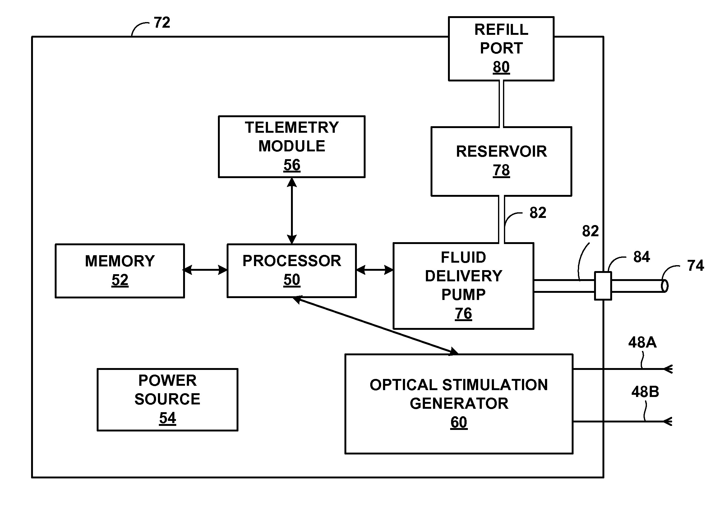
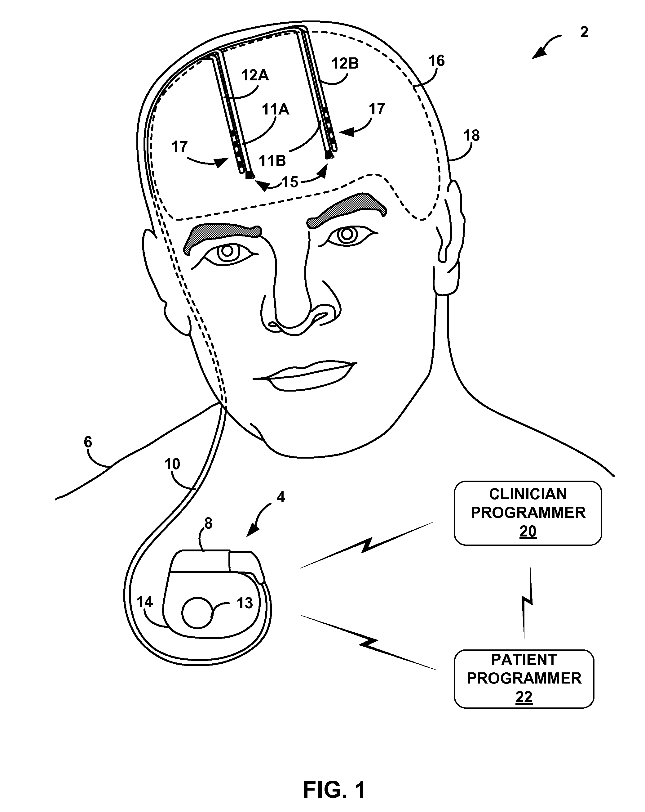
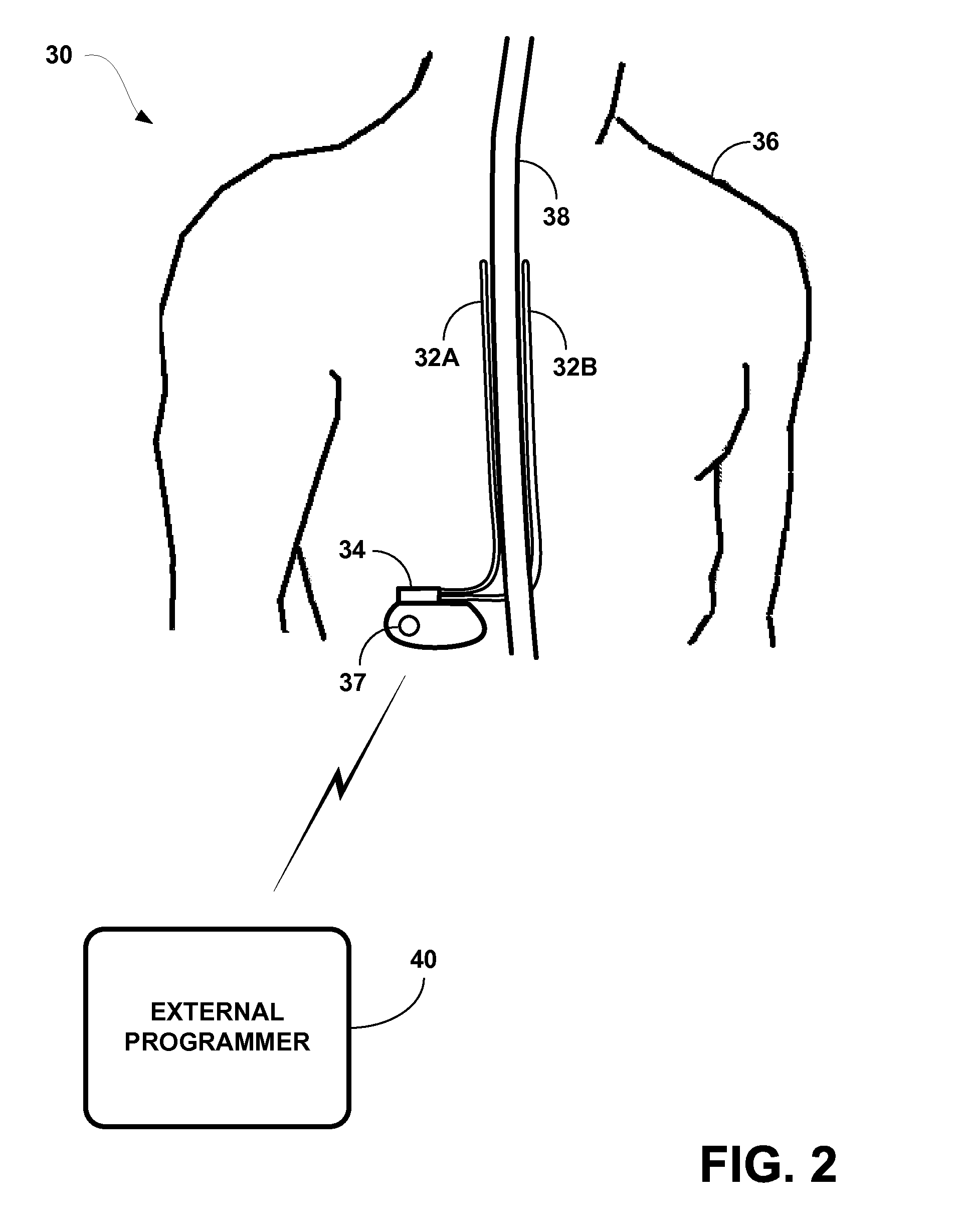
The disclosure, in some examples, describes optical stimulation techniques, such as optogenetic stimulation techniques. The techniques may be capable of exciting or inhibiting neural activity in target neuron populations. For optogenetic stimulation, the target neurons may be selectively transfected with genes that express opsins that are activated by light emitted into the target tissue. The light may be selected to activate an opsin to initiate neuronal spikes or to deactivate or inhibit an opsin to cease or prevent neuronal spikes. The light may also be selected to activate an opsin to suppress a neuronal spike. An optogenetic stimulation system may be configured as an implantable medical device that can deliver optical stimulation through implantable optical fibers or other light-delivery apparatus to a target tissue, such as to specific or highly specific neuron populations. The high degree of specificity provided by the optical stimulation may limit or prevent stimulation of n...


PUM


Abstract

Methods of delivering optical stimulation to a target tissue from an optical stimulation device are provided. One method comprises sensing a temperature at the optical stimulation device or proximate to the optical stimulation device, and adjusting the delivery of light to the target tissue based on the sensed temperature. Another method comprises delivering the light to the target tissue with an optical light guide and sensing bioelectric signals with a sense electrode, wherein the optical light guide and the sense electrode each comprise a material that produces substantially no induced current in an electromagnetic field. Another method comprises delivering light from a light source of an optical stimulation device to a window of the optical stimulation device, delivering the light from the window to an optical light guide optically connected to the window, and delivering the light to a target tissue via the optical light guide.

Description

STATEMENT REGARDING SEQUENCE LISTINGThe Sequence Listing in accordance with 37 C.F.R. §§1.821-1.824 associated with this application is provided in text format in lieu of a paper copy, and is hereby incorporated by reference into the specification in its entirety. The name of the text file containing the Sequence Listing is “SEQUENCELISTING.txt.” The text file is 18 KB, was created on Feb. 5, 2010, and is being submitted electronically via EFS-Web.TECHNICAL FIELDThe disclosure relates to optical stimulation therapy.BACKGROUNDElectrical stimulation of neural tissue serves as the core of many neurological therapies, and can provide relief for a variety of disorders, improving the quality of life for many patients. In some cases, electrical stimulation may be characterized by a lack of specificity in the excitation of neural tissue. In particular, it can be difficult to stimulate a specific, localized neural population due to constraints on electrode geometry and placement. For example...

Claims


Application Information

Patent Timeline
Patent Type & Authority Applications(United States)
IPC IPC(8): A61N5/06A61N1/36A61M37/00
CPCA61B2017/00084A61M5/14276A61N1/365A61N5/0601A61N5/0622A61N5/062A61N2005/063A61N2005/0651A61B2018/00839A61N2005/0612A61N2001/086A61N1/086A61N2005/0626
Inventor DENISON, TIMOTHY J.PARALIKAR, KUNALMUNNS, GORDON O.SANTA, WESLEY A.CONG, PENGNIELSEN, CHRISTIAN S.NORTON, JOHN D.
Owner MEDTRONIC INC
Why Eureka
Try Eureka