
System for controlling ultrasonic clamping and cutting instruments

a technology of clamping and cutting instruments, applied in the direction of electric generator control, tomography, therapy, etc., can solve the problems of unfavorable tissue hemostasis, unfavorable tissue hemostasis, and high power delivered to the tissue,

Active Publication Date: 2008-02-26
CILAG GMBH INT
View PDF14 Cites 347 Cited by
  • Summary
  • Abstract
  • Description
  • Claims
  • Application Information

AI Technical Summary

Benefits of technology

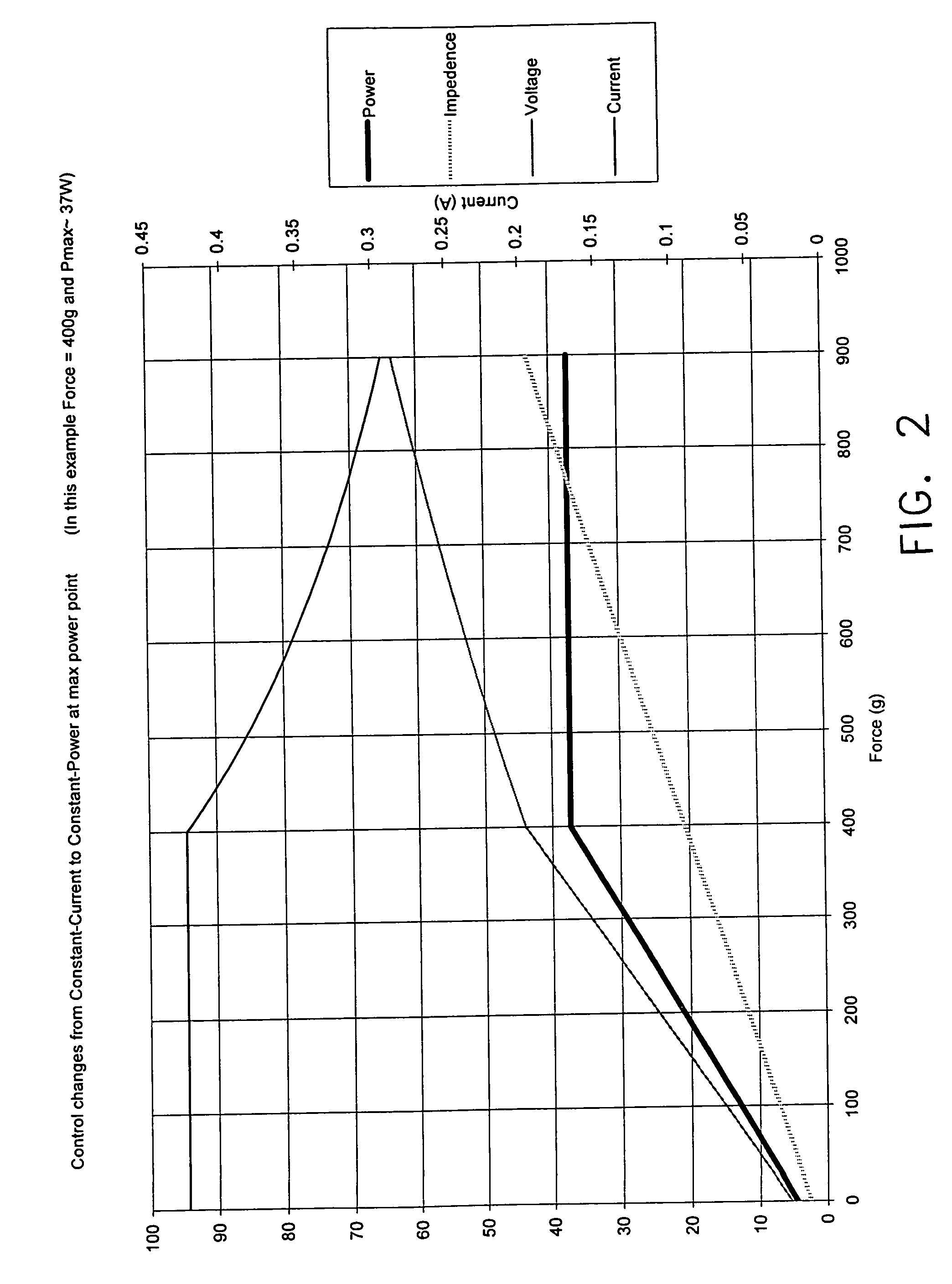
The present invention provides a control system for an ultrasonic surgical instrument that maintains constant power output as long as a certain pressure threshold is met. This control system ensures safe and reliable use of the ultrasonic surgical instrument. Additionally, the invention provides an ultrasonic surgical system that includes the control system and an instrument with an ultrasonic transducer and an end effector. The method for controlling the application of power by the ultrasonic surgical instrument involves adjusting the current and voltage to maintain the power output at the desired level. Overall, the invention improves the precision and efficiency of ultrasonic surgery.

Problems solved by technology

However, they are highly responsive to the pressure applied by the surgeon.
In fact, in situations where a surgeon exceeds a predetermined pressure level, the power delivered to the tissue may be too high.
This may result in undesired tissue effects, such as poor hemostasis of transacted vessels.
Furthermore, it is possible that the surgical instrument might not be equipped to handle the material stress requirements for producing the vibration levels at the high pressure levels, thus resulting in undesirable operation of the instrument.
However, these attempts have been met with only limited success.

Method used


Image

  • System for controlling ultrasonic clamping and cutting instruments
  • System for controlling ultrasonic clamping and cutting instruments
  • System for controlling ultrasonic clamping and cutting instruments

Examples


Embodiment Construction

[0016]The detailed embodiment of the present invention is disclosed herein. It should be understood, however, that the disclosed embodiment is merely exemplary of the invention, which may be embodied in various forms. Therefore, the details disclosed herein are not to be interpreted as limited, but merely as the basis for the claims and as a basis for teaching one skilled in the art how to make and / or use the invention.

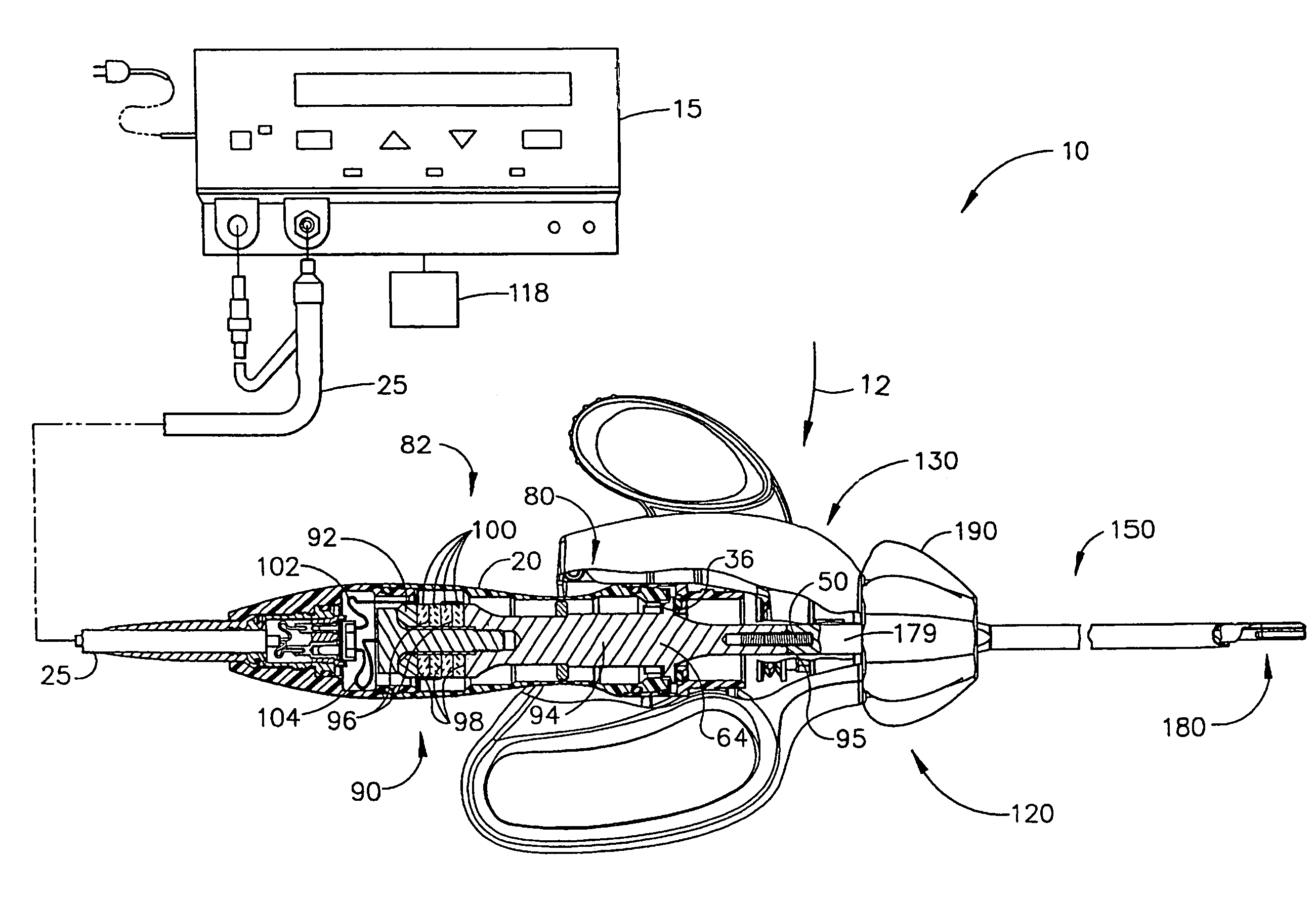
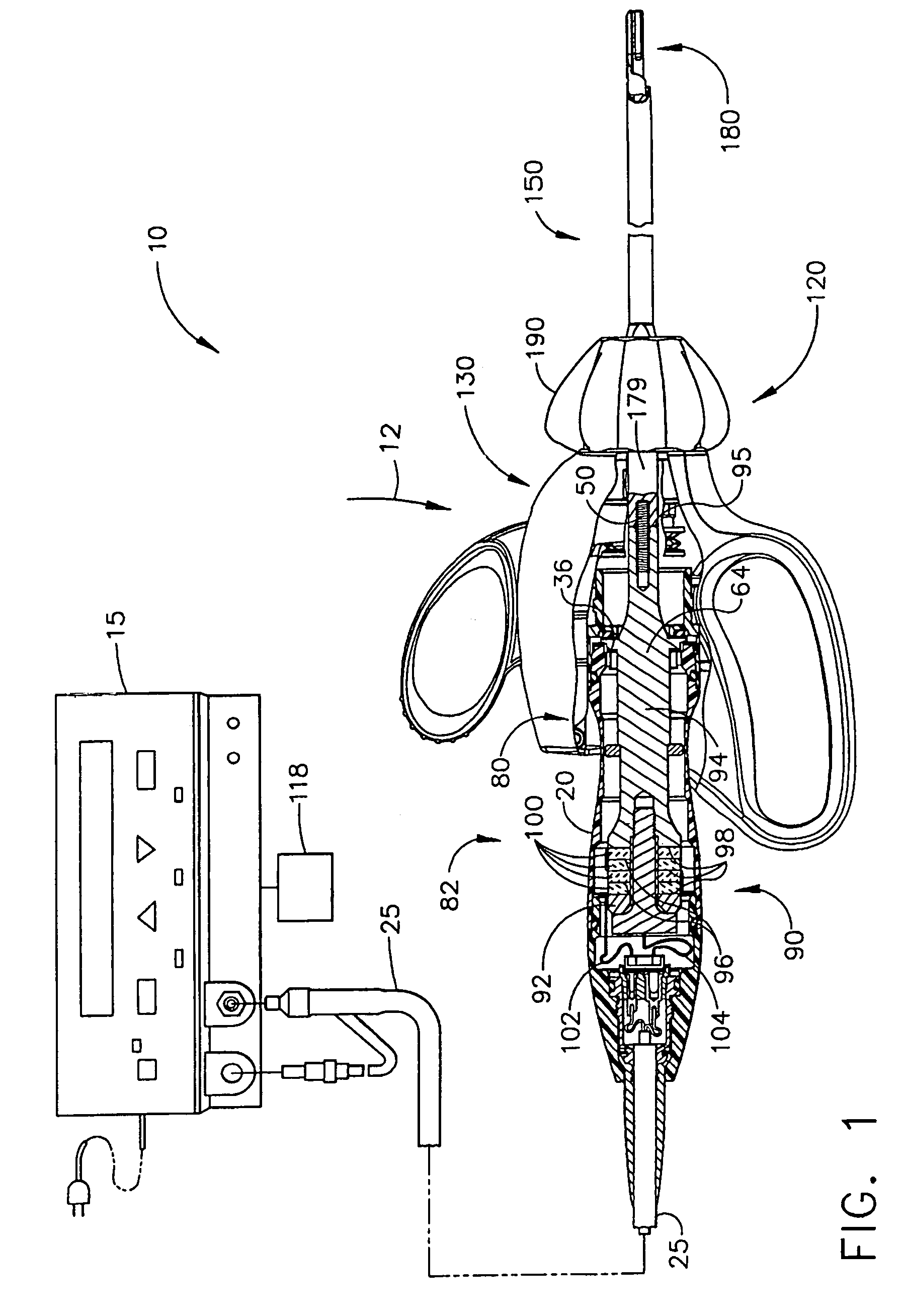
[0017]With reference to FIG. 1, an ultrasonic system 10 for use in conjunction with ultrasonic surgical clamping and cutting instruments 12 is disclosed. In accordance with a preferred embodiment of the present invention the ultrasonic system 10 includes an ultrasonic signal generator 15 adapted for applying current and voltage sufficient to maintain power substantially constant during the procedure.

[0018]In accordance with a preferred embodiment of the present invention, the system is adapted for working with an ultrasonic instrument 12 similar to that disclosed in U...


PUM


Abstract

A control system for use with an ultrasonic surgical instrument includes a generator supplying electrical energy to an ultrasonic surgical instrument, the electrical energy supplied by the generator being controlled such that power applied by the instrument is maintained constant once a predetermined pressure threshold is met. The control system operates by assigning a nominal power at which the ultrasonic instrument is to operate and adjusting the current and voltage applied to the ultrasonic surgical instrument so as to maintain the power applied by the ultrasonic surgical instrument at approximately the nominal power.

Description

BACKGROUND OF THE INVENTION[0001]1. Field of the Invention[0002]The invention relates to ultrasonic surgical clamping and cutting instruments. More particularly, the invention relates to an improved power limiting mechanism for ultrasonic surgical cutting and clamping instruments.[0003]2. Description of the Prior Art[0004]Ultrasonic instruments are used for the safe and effective treatment of many medical conditions. Ultrasonic instruments are advantageous because they may be used to cut and / or coagulate organic tissue using energy in the form of mechanical vibrations transmitted to a surgical end-effector at ultrasonic frequencies.[0005]Ultrasonic vibrations, when transmitted to organic tissue at suitable energy levels and using a suitable end-effector, may be used to cut and / or dissect tissue. Ultrasonic instruments utilizing solid core technology are particularly advantageous, because of the amount of ultrasonic energy that may be transmitted from the ultrasonic transducer throug...

Claims


Application Information

Patent Timeline
Patent Type & Authority Patents(United States)
IPC IPC(8): A61B17/32H02P9/04
CPCA61B17/320092A61B2017/00017A61B2017/00026A61B2017/00106A61B2017/0011A61B2017/320095A61B2017/320094A61B18/18A61N7/00A61B18/12
Inventor WIENER, EITAN T.
Owner CILAG GMBH INT
Learn More